
 İngilizce
 中文简体
中文简体 Русский
 Español
 Português
 Türkçe
 العربية
 Deutsch
 Polski
 Italiano
 Français
 한국어
한국어 ไทย
ไทย Tiếng Việt
 日本語
日本語





























Koni Kalorimetresi
Kullanım Kılavuzu
uygulanabilir LISUN modeller: LS-ISO5660
1. Ekipman Hakkında Temel Bilgiler
1.1 Equipment Assembly
1.1.1 Kutudan Çıkarma
There are two wooden crates in total. The small wooden crate contains the combustion platform; everything else is in the large wooden crate. Please unpack everything carefully.
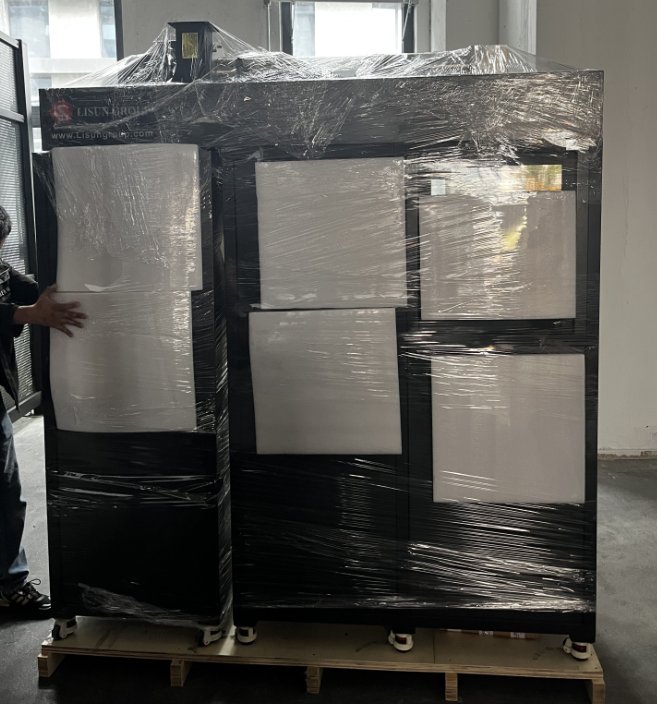
The following are the hosts:
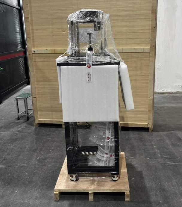
The following is the combustion platform:
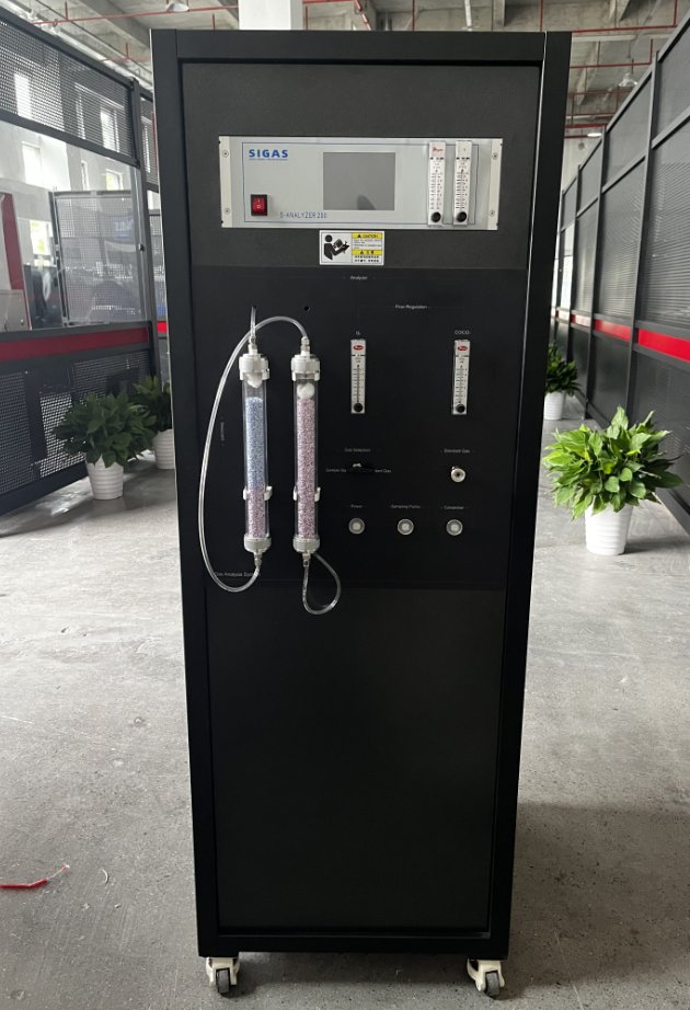
The following is a gas analysis cabinet:
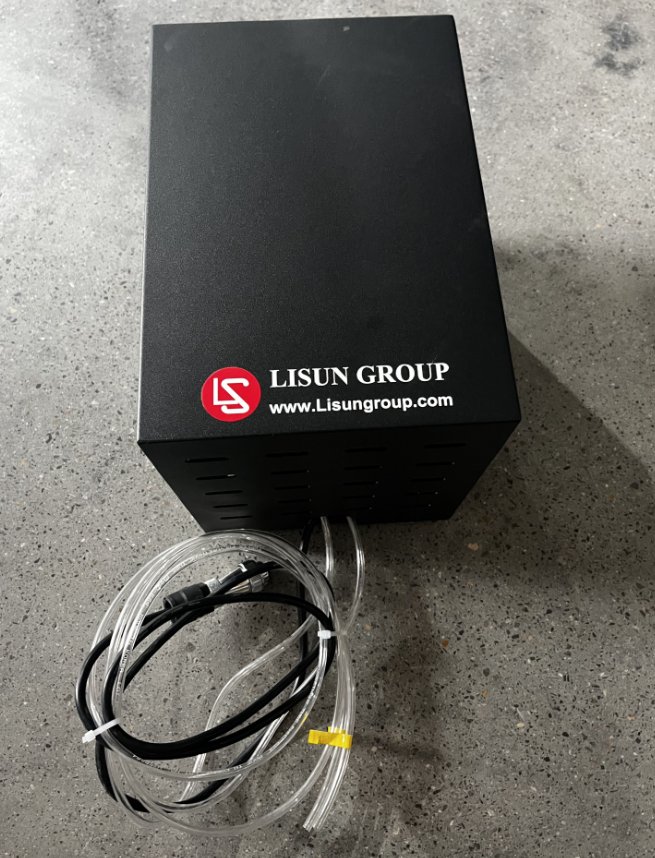
The following are air pumps:
1.1.2 Assembling The Host System
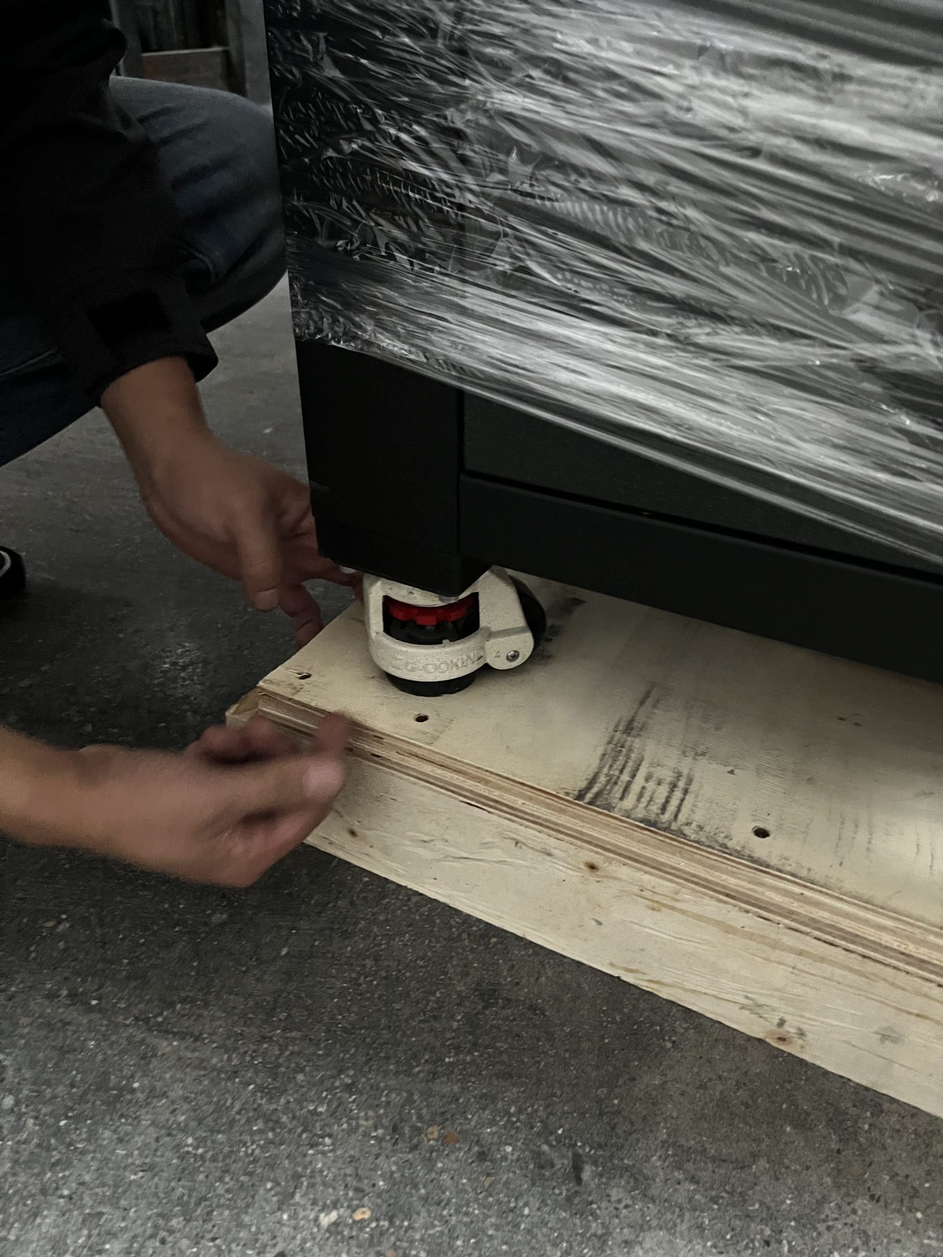
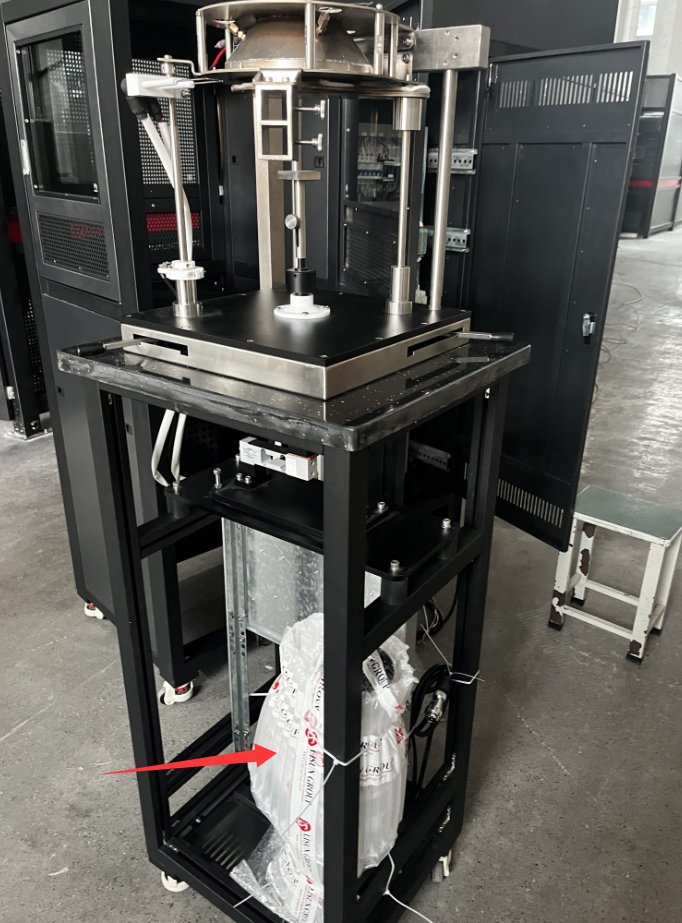
The wheels on the bottom of the unit are locked; turn them clockwise to unlock them:
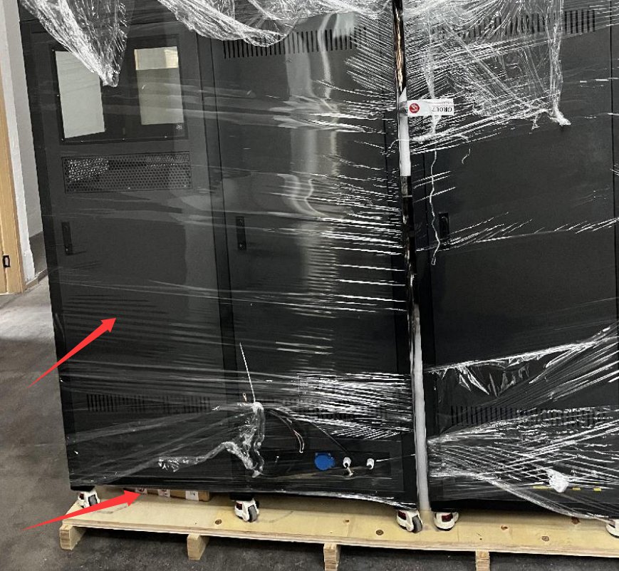
There is a cardboard box containing the parts here. You can open the rear door first and remove the box of parts:
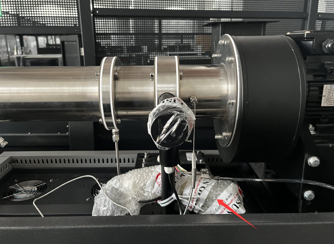
One end of the optical path has been disassembled and is placed here:
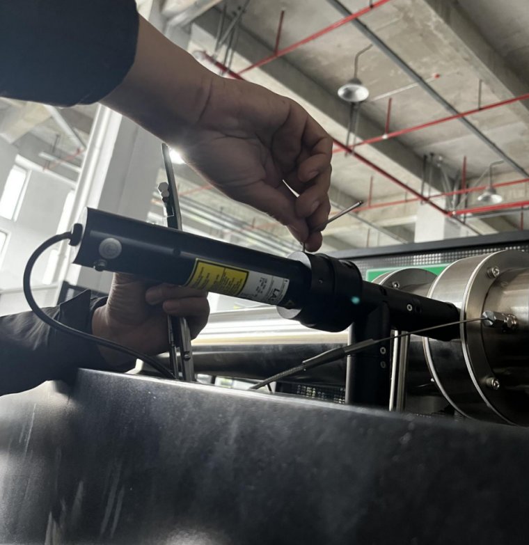
Simply install it in the following location:
Unpack the pre-packaged tobacco pipes and accessories:
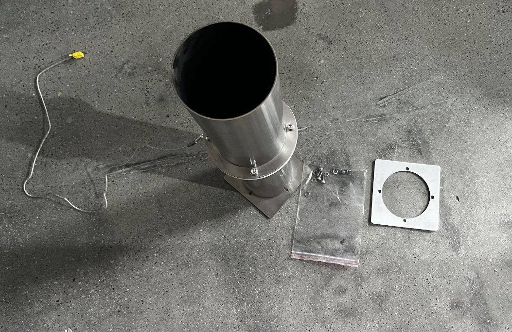
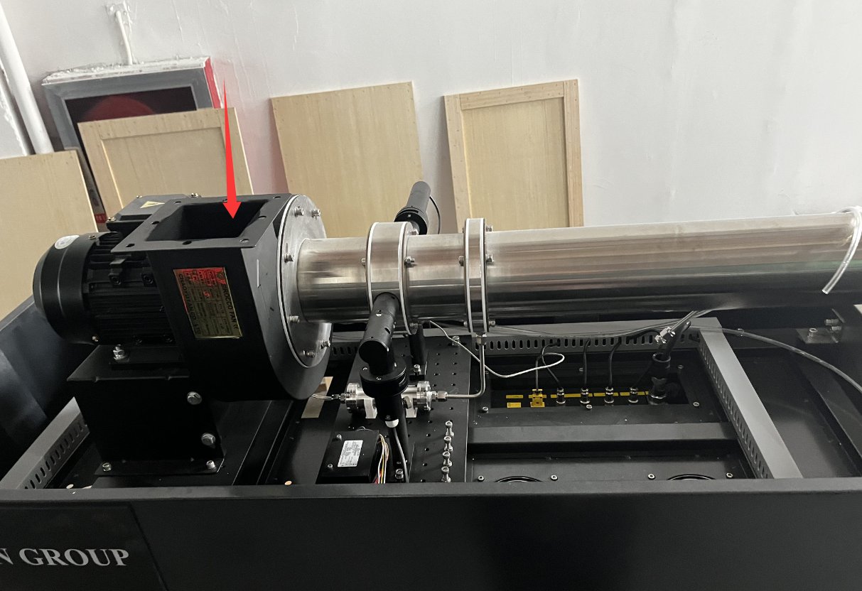
Buraya yükleyin:
Connect the thermocouple plug from the flue pipe to “to 2”:
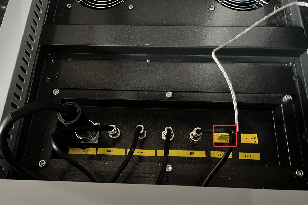
The thermocouple at the “to 1” connection may have come loose during packaging. Reconnect the thermocouple plug shown in the figure below to “to 1”:
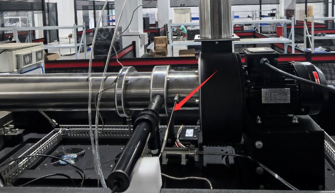
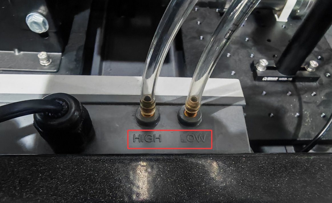
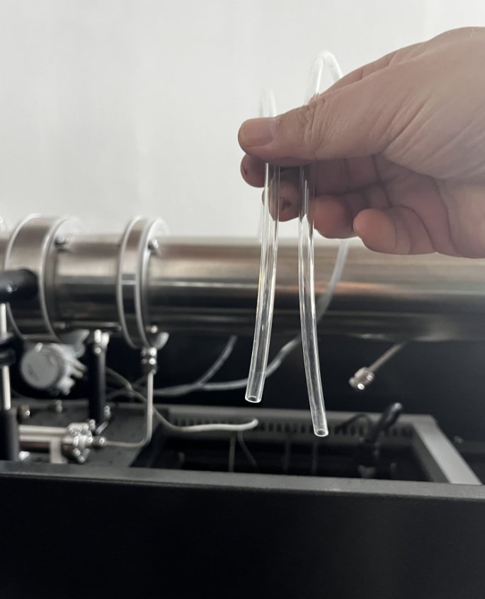
Connect the flue gas hoses as follows: the hose labeled “HIGH” should be connected to the lower metal pipe of the flue, and the hose labeled “LOW” should be connected to the upper metal pipe of the flue:
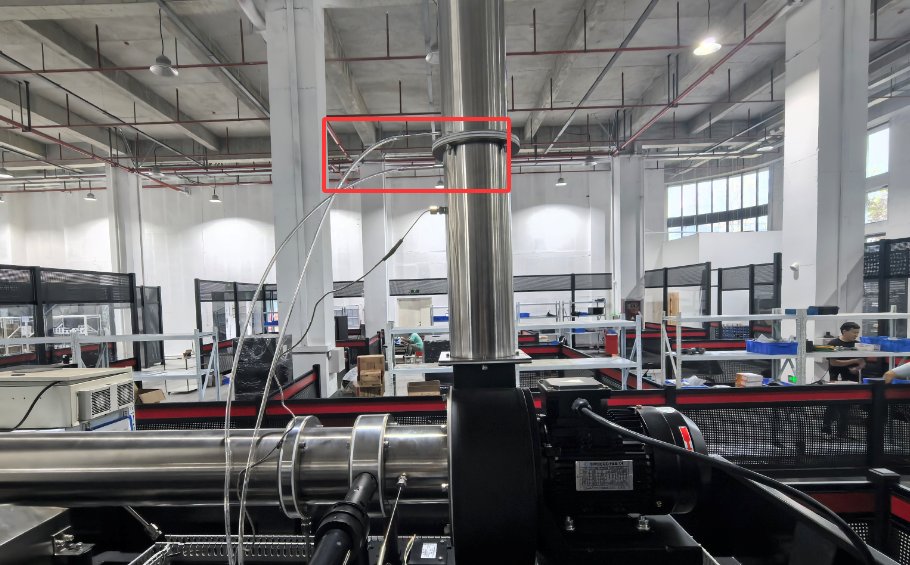
During the test, smoke will be emitted from the other end of the smoke duct; please ensure it is properly vented to the outdoors as required by the site conditions.
1.1.3 Assembly of the Combustion Platform
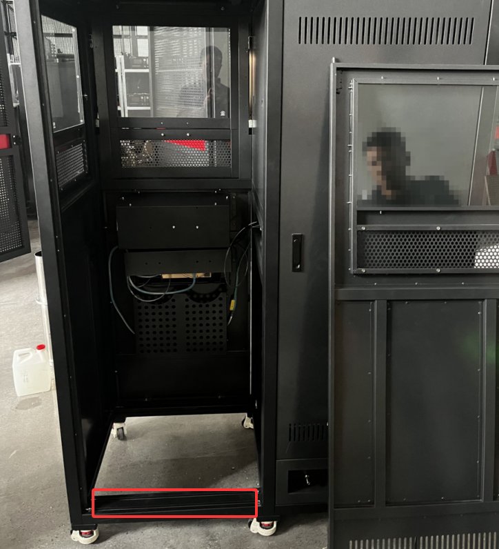
Remove the crossbeam here, then slide the combustion platform into place:
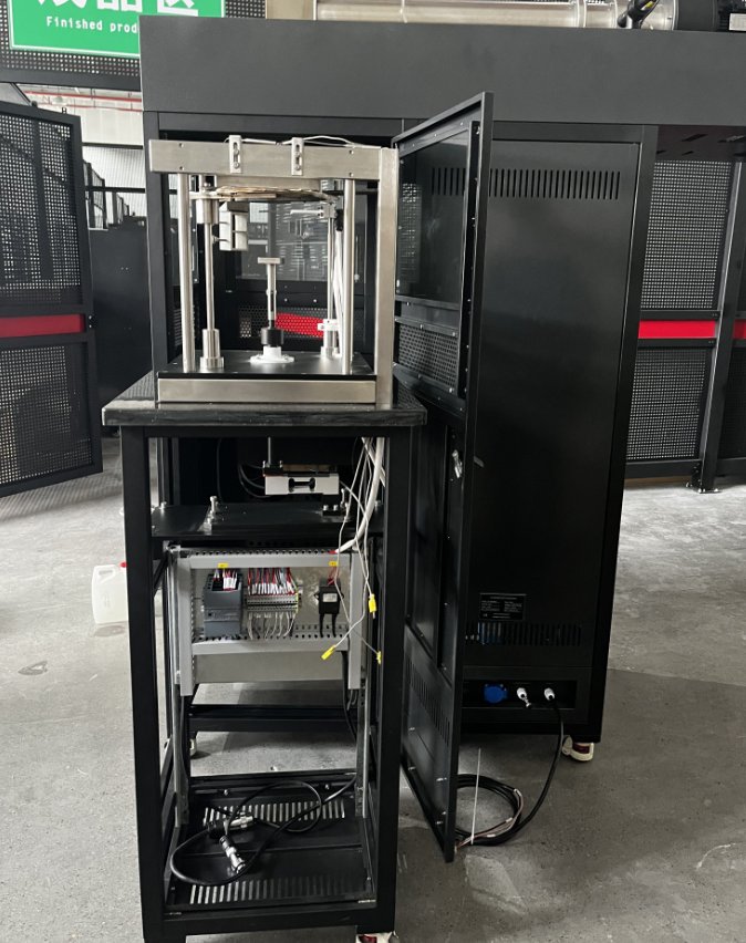
Connect all the cables from the combustion platform to the host computer; there is no need to distinguish between the three thermocouples:
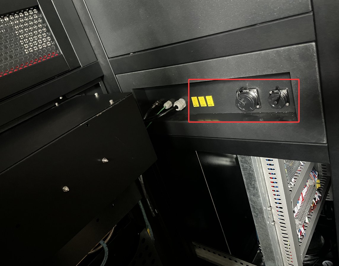
Then reinstall the removed crossbeam.
1.1.4 Assembly of the Gas Analysis Cabinet
Move it directly to the following location:
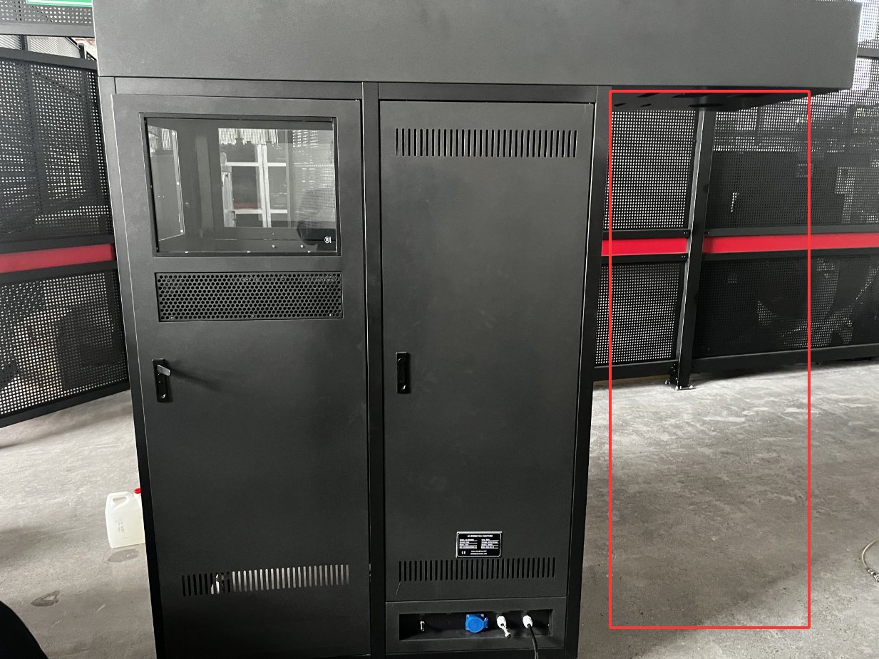
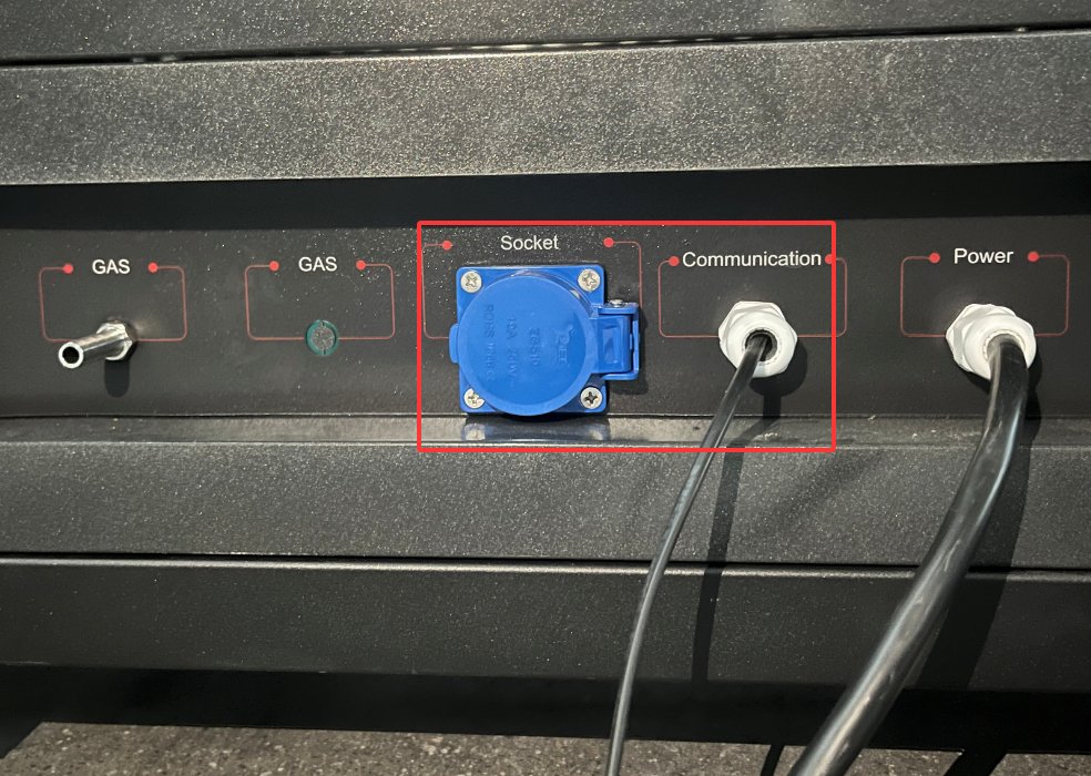
The gas analysis cabinet has the following two wires:
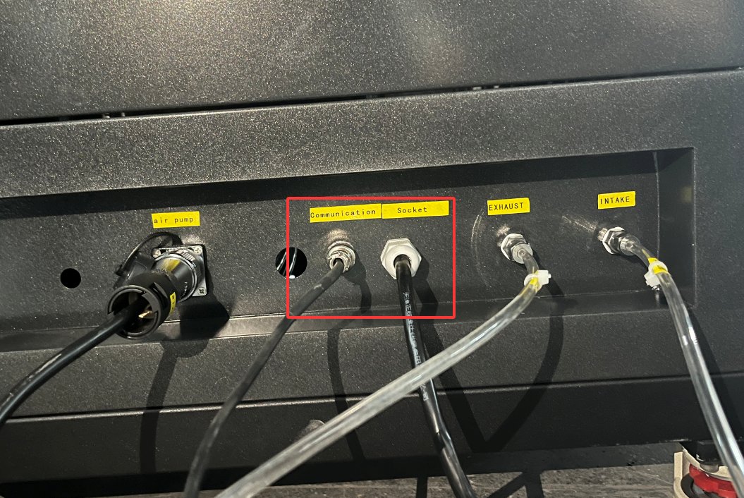
Connect the following two cables to the host: one is the communication cable, and the other is the power cable:
1.1.5 Air Compressor Assembly
The following image shows an air pump:
Connect the power cord and air hose to the back of the gas analyzer cabinet as indicated; see the figure below:
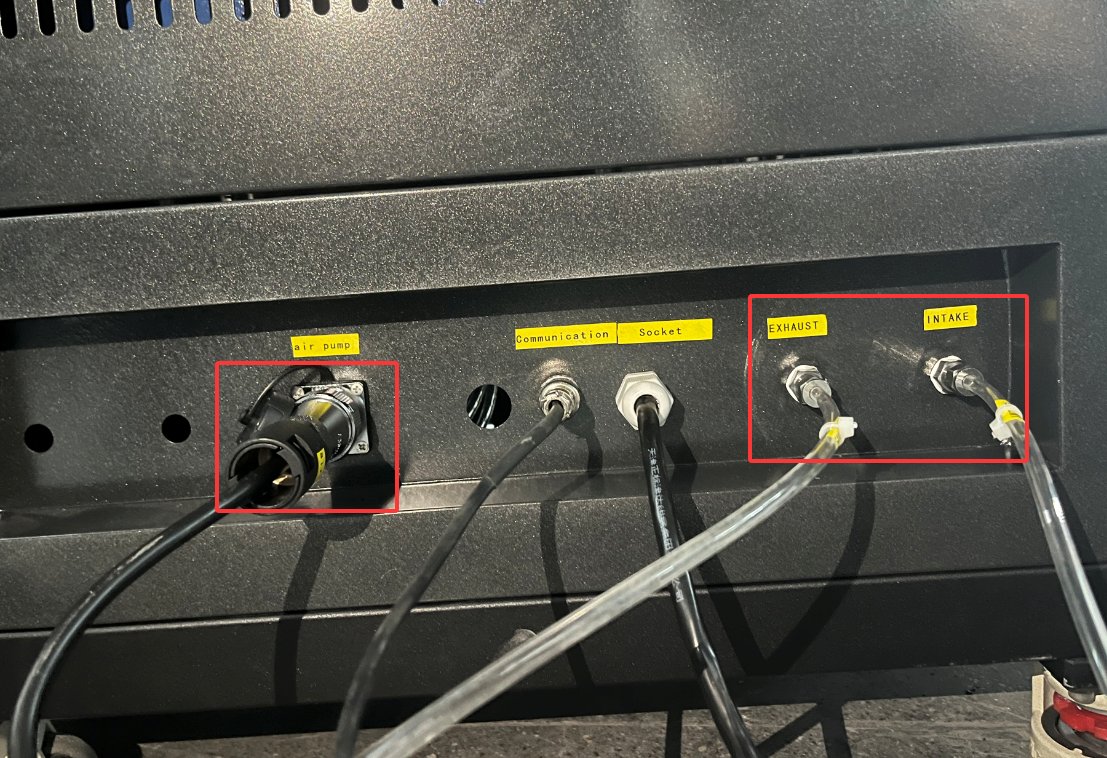
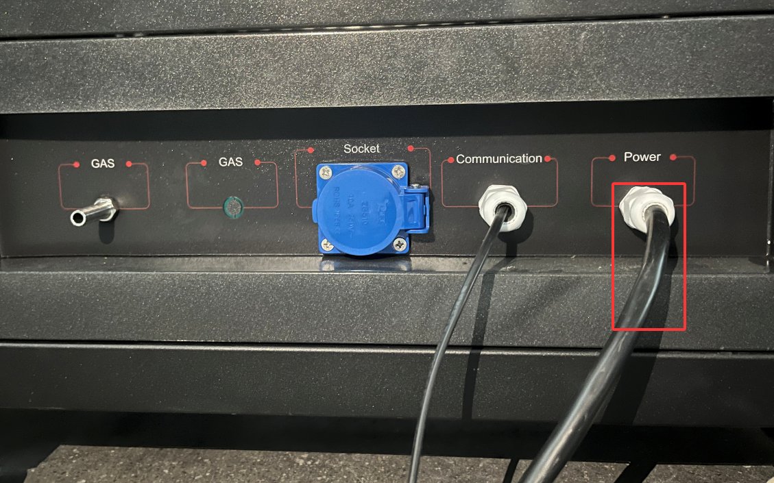
This way, the host’s power cord can supply power to all devices in the system, as shown in the figure below:
1.2 Equipment Composition and Functional Classification
1.2.1 Çekirdek Modül
The equipment consists of four core modules: a standard gas analysis cabinet, a test control cabinet, a combustion test platform, and a measurement section. Each module has a specific function and works in coordination with the others:
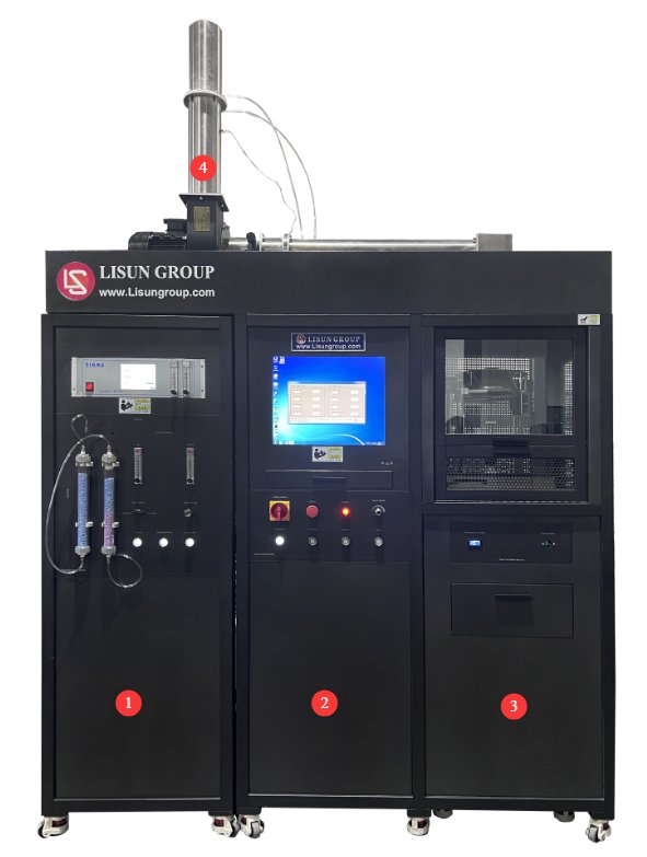
① Standard Gas Analysis Cabinet: Responsible for flue gas sampling, filtration, condensation, and component analysis. It integrates core components such as a pressure-regulating valve, a Schutz condenser, and a sampling pump; the sampling lines are made of 316 stainless steel to ensure gas purity. The front panel integrates a desiccant, sample gas/calibration gas selection valves, a rotameter, and control buttons for the power supply and sampling pump; the rear panel houses the power and communication cables, allowing the unit to function as a standalone device compatible with other heat release testing systems.
② Test Control Cabinet: Responsible for circuit integration, functional control, and data display. It features a built-in Siemens PLC control system to enable data acquisition and integrated equipment control; it is equipped with a 19-inch industrial all-in-one touchscreen computer and a wireless mouse and keyboard, and includes built-in host computer control software. The front panel integrates the main power switch, emergency stop button, speed control knob, and controls for the blower, heater, and ignition; the rear panel features reserved ports for the gas inlet pipe, a power outlet for the standard gas cabinet, and communication interfaces; the side panel is equipped with aviation connectors for controlling the combustion test cabinet and quick-connect interfaces for thermocouples.
③ Combustion Test Platform: Provides a test environment for sample combustion. It integrates a heated radiation hood (including three temperature-measuring thermocouples), a Siemens weighing system, a high-pressure ignition device, and a marble work surface, allowing the sample mounting frame to be placed directly on it and enabling real-time weighing.
④ Measurement Section: This section includes components such as the smoke collection hood, exhaust duct, exhaust fan, optical path testing system, sampling system, differential pressure testing system, and temperature testing system. It can be removed as a single unit, reducing transportation difficulties and improving maintenance efficiency.
1.2.2 Temel Bileşenler
Radiation Cone: Rated power 5000 W, heat flux 0–100 kW/m², regulated by a PID temperature controller (integrated into the Siemens PLC); can be positioned horizontally or vertically; irradiation deviation on a 50 × 50 mm area at the center of the exposed test specimen surface is ≤ ±2%.
Gaz Analizörleri: Includes paramagnetic oxygen analyzers, CO₂ analyzers, and CO analyzers. Oxygen analyzer measurement range: 0–25%; T90 < 1.5 s; zero drift and measurement offset both < 0.5%/month; linearity error < 1% of the current range; CO₂ analyzer measurement range: 0–10%; drift and noise are both < 100 ppm; CO analyzer measurement range: 0–1%; drift and noise are both < 20 ppm.
Tartı sistemi: Weighing range 0–3000 g, display accuracy 0.01 g, measurement accuracy 0.1 g; capable of real-time monitoring of mass changes during the combustion of test specimens.
ateşleyici: A high-voltage spark generator equipped with a safety shut-off device, with an output voltage of 10 kV. It features automatic positioning; the gap between the ignition needle and the nozzle must be adjusted to 3–5 mm.
Optik sistem: Includes a laser transmitter, receiver, and transmittance calibration components. It is used to measure the transmittance of flue gas to calculate smoke opacity and requires periodic 100%/0%/50% transmittance calibration.
1.2.3 Yardımcı Sistem
Egzoz sistemi: Consists of a fan, a smoke hood, intake and exhaust ducts, and an orifice plate flowmeter. The smoke exhaust fan has a flow rate range of 0 to 0.034 m³/s; the exhaust flow rate is determined by measuring the pressure difference across a sharp-edged orifice plate (inner diameter 57 mm ± 1 mm) located 350 mm above the fan; The annular sampler is located within the intake duct 685 mm from the fume hood and features 12 small holes to homogenize the gas stream composition.
Soğutma Sistemi: Includes a factory-installed portable water-cooling system (designed specifically for heat flux meters; no external tap water connection required) and a Schütz condenser (condensation temperature: 0–5°C, equipped with an automatic peristaltic pump for drainage), which effectively controls the temperature of the equipment and flue gas.
Veri Toplama Yazılımı: Records output data from devices such as oxygen analyzers, orifice flow meters, and thermocouples; automatically calculates parameters such as heat release rate and mass loss rate; and generates test curves and reports.
1.2.4 Introduction to Accessories
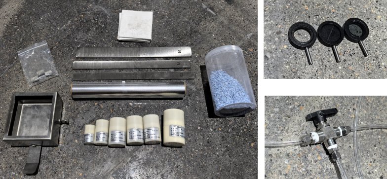
Sample Accessories: Sample holder (for samples measuring 100 mm × 100 mm × ≤50 mm), sample holder, aluminum foil with a thickness of 0.025–0.04 mm, a layer of refractory fiber with a thickness of 13 mm and a density of 65 kg/m² (1–2 layers), steel rulers with heights of 23 mm, 25 mm, and 35 mm, and a gas T-fitting.
Calibration accessories: 250 g/50 g/100 g/200 g standard weights (accuracy ±0.1 g), 0%/50%/100% transmittance shutters.
Sarf Malzemeleri ve Aksesuarlar: Anhydrous calcium sulfate desiccant, gas filter cartridges, etc.
1.3 Temel Teknik İlkeler
1.3.1 The Core Principle of Oxygen Consumption
The core testing principle of the Cone Calorimeter is the oxygen consumption principle: the heat released when a material burns is essentially constant per unit mass of oxygen consumed. According to the findings of Hugget’s 1980 study, plastics and other solid materials commonly used in the construction and commercial sectors adhere to this principle, with a value of 13.1 MJ/kg ± 5% (the validity of this value is confirmed by ISO 5660-1-2015).
In the test, the flue gas produced by combustion is collected by a hood and thoroughly mixed in the exhaust pipe; the mass flow rate is then measured using an orifice plate flowmeter, and the concentrations of O₂, CO₂, and CO are detected by a gas analyzer. By calculating the mass of oxygen consumed during combustion and applying the standard oxygen consumption value, the heat release rate of the material can be derived. The formula is simplified as follows:
Heat Release Rate (HRR) = Mass of oxygen consumed × 13.1 MJ/kg
1.3.2 Measurement Logic for Key Parameters
Isı Yayın Oranı (HRR): This is a key parameter for evaluating a material’s combustion intensity, calculated by determining oxygen consumption based on changes in oxygen concentration and exhaust gas flow rate, and then derived using a standard oxygen consumption value.
Kütle Kaybı Oranı (MLR): Calculated by dividing the change in the specimen’s mass—monitored in real time by a weighing system—by the specimen’s area and time, this value reflects the rate of mass loss during the material’s combustion process.
Duman Yoğunluğu: Measured by determining the percentage of the laser beam obscured by smoke using an optical system, and calculated in conjunction with the exhaust flow rate to characterize a material’s smoke-producing capacity during combustion.
C – Coefficient: Calibrates the system response by calibrating the burner (methane combustion) to correct for systematic errors in gas analysis and flow measurement, ensuring the accuracy of HRR calculations.
1.4 Referenced Standards and Key Terms
1.4.1 Temel Standartlar
ISO 5660-1-2015: “Fire Performance of Building Materials and Products—Part 1: Determination of Heat Release Rate, Smoke Density, and Mass Loss Using a Cone Calorimeter.”
GB / T 16172-2007: “Test Method for Heat Release Rate of Building Materials.”
ISO 554: “Standard Environments for Calibration and Testing.”
GB / T 2918: “Standard Environmental Conditions for Conditioning and Testing of Plastic Specimens.”
ISO 13943: “Fire Safety.”
ISO / TR 14697: “Guidance on the Selection of Substrates for Building Products.”
1.4.2 Basic Terminology
Basic Surface Flatness: The deviation between any uneven areas on the specimen’s surface and the reference plane shall be ≤ ±1 mm.
Flash ignition: A combustion phenomenon in which a flame appears on or above the surface of a test specimen and lasts for less than 1 second.
Ateşleme: The phenomenon in which a sustained flame appears on or above the surface of a test specimen.
parlama: The ratio of the radiant flux incident on a surface element at a given point on the specimen’s surface to the area of that surface element, measured in kW/m².
Sustained Combustion: A combustion phenomenon in which the flame burns for more than 10 seconds.
Brief Combustion: A combustion phenomenon in which the flame lasts between 1 and 10 seconds.
C – Coefficient: A calibration constant used to correct system response deviations; the typical range is 0.038 to 0.045.
Constant Weight: The difference in mass between two weighings taken 24 hours apart must be ≤ 0.1% of the specimen’s mass or 0.1 g (whichever is greater).
2. Preparations Before the Experiment
2.1 Preliminary Check of the Environment and Equipment
2.1.1 Çevresel Koşulların Doğrulanması
In accordance with the ISO 554 standard, the test environment must meet the following requirements: Temperature: (23±2) °C; Relative humidity: (50±5) %; Environmental cleanliness: No noticeable dust or corrosive gases; direct airflow onto the combustion test platform must be avoided.
2.1.2 Equipment Status Verification
Egzoz sistemi: Check that the fume hood and exhaust duct are clear and free of obstructions; turn on the fan, listen for normal operating sounds, and verify that the exhaust system is functioning properly.
Pipe Leak Tightness: If the separator or filter of the gas sampling system was disassembled after the previous test, a leak test must be performed: Turn on the sampling pump and introduce pure nitrogen at the same flow rate and pressure as the sample gas (cylinder pressure < 0.2 MPa); the oxygen analyzer reading should be close to zero.
Bileşen Bütünlüğü: Check that key components—such as the radiation cone, igniter, thermocouple, and heat flux meter—are in good condition and free of deformation, damage, or looseness.
Soğutma Sistemi: Verify that the condenser water level is normal and that the diaphragm pump is draining properly; ensure that the portable water cooling system has sufficient water and no leaks.
2.1.3 Power Supply Check
A single-phase, three-wire power supply with a minimum current rating of 32 A and no ground fault circuit interrupter (GFCI) must be used, and the equipment housing must be reliably grounded (ground resistance < 4 Ω) to prevent ground faults or electromagnetic interference from affecting test accuracy.
Check that the power outlets and wiring are free of damage and securely connected to ensure a stable power supply to the equipment.
2.2 Preparation of Reagents and Supplies
2.2.1 Standard Gases and Reagents
|
İsim |
Spesifikasyon Gereksinimleri |
Kullanımlar |
Önemli Notlar |
|
saf azot |
Saflık ≥ %99.99 |
Zero-Point Calibration of Gas Analyzers and Pipeline Leak Detection |
Stored in pressure-resistant cylinders; operating pressure ≤ 0.2 MPa |
|
Metan gazı |
Saflık ≥ %99.5 |
Calibration of Heat Release Rate |
Flammable gas; keep away from sources of ignition; adjust the cylinder pressure to 0.15 MPa. |
|
Standard Mixture |
O₂: 20.5%, CO₂: 8.5%, CO: 0.85% (balance N₂) |
High-Point Calibration of a Gas Analyzer |
Use within the expiration date and keep out of direct sunlight. |
|
Anhydrous calcium sulfate |
Analitik Sınıf |
Desiccant, used for gas dehydration |
Replace immediately after discoloration to ensure the stability of the gas analyzer. |
2.2.2 Auxiliary Materials for Test Specimens
Alüminyum folyo: Thickness 0.025–0.04 mm, pre-cut to a size slightly larger than the test specimen (it must cover the bottom and sides, extending 3 mm beyond the top surface).
Refractory fiber layer: 13 mm thick, 65 kg/m² density; must be cut to fit the positioning frame; use 1–2 layers per application.
Temel malzeme: An inert material compatible with the specimen’s intended service environment (e.g., calcium silicate board); adjust the thickness as needed to ensure the total thickness of the specimen is ≥6 mm (for specimens thinner than 6 mm).
Temizlik malzemeleri: lint-free cloth, alcohol (for removing oil or impurities from the surface of the test specimen).
2.3 Güvenlik Önlemleri
2.3.1 Kişisel Koruyucu Ekipman
Operatörler şunları giymelidir: heat-resistant protective gloves (when handling high-temperature components such as the radiation cone and specimen mounting frame) and koruma gözlüğü (to protect against splashes of molten specimen material or debris).
Long hair must be tied back; do not wear loose clothing or jewelry to prevent them from getting caught in equipment or coming into contact with high-temperature components.
2.3.2 Risk Alerts
Gaz Kaçak Tespiti: Before the test, apply soapy water to the methane gas line connections and check for bubbles; if you smell a gas odor, immediately close the cylinder valve, open the laboratory doors and windows to ventilate the area, and do not light any flames or operate electrical switches. Wait until the odor dissipates before locating the leak.
Yüksek Voltaj Uyarısı: The igniter outputs 10 kV. Do not touch the ignition needle or high-voltage leads during testing to avoid electric shock. If ignition fails, turn off the ignition switch before inspecting the unit.
Yüksek Sıcaklık Uyarısı: The surface temperature of the radiation cone becomes extremely high during operation; do not touch it without protective gear. After testing, allow the equipment to cool to room temperature (≤50°C) before cleaning or performing maintenance.
Ventilation Warning: Ensure that the building’s ventilation system has sufficient capacity to promptly exhaust toxic and harmful gases (such as CO) produced by combustion to the outdoors. Laboratories must be equipped with toxic gas detectors.
3. Equipment Calibration (Core Commissioning Process)
3.1 Calibration of the Gas Analyzer (The analyzer must be turned on 24 hours in advance to allow for warm-up; calibration is required once upon initial startup or after a shutdown; if the device is left on continuously, calibration should be performed once a week)
3.1.1 Calibration of the CO₂ Zero and Span Points
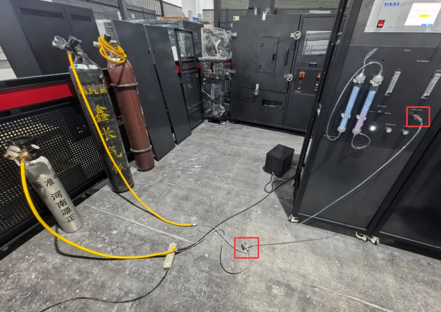
Connect the nitrogen cylinder and the mixed gas cylinder to the gas manifold, respectively, and then connect the manifold to the “calibration gas port”:
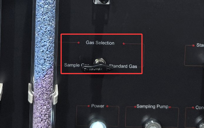
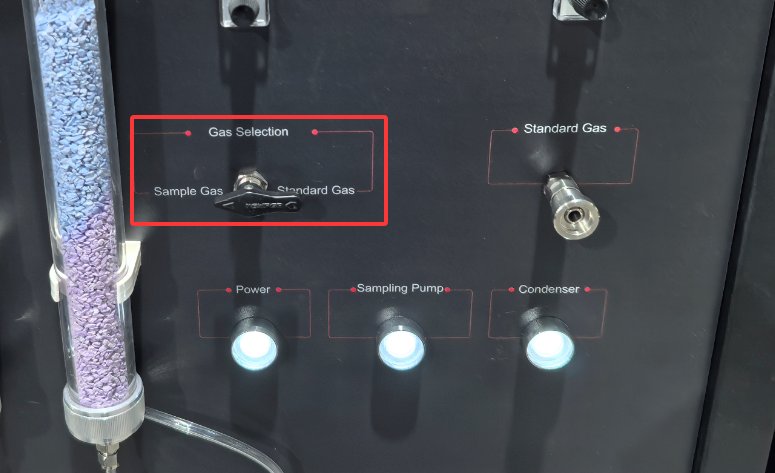
Gas selector switch, set to “calibration gas”:
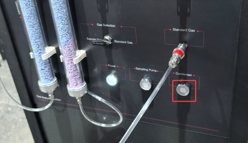
Start the condenser: (Note: The sampling pump does not need to be turned on when calibrating the gas analyzer.)
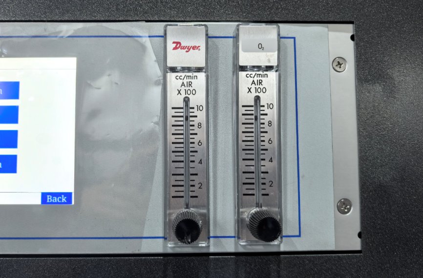
Switch the gas T-joint to nitrogen, open the nitrogen valve, and slowly adjust the pressure regulator so that the flow rates of the analyzer’s “O₂” and “CO/CO₂” rotameters stabilize at 800–900 cc/min.
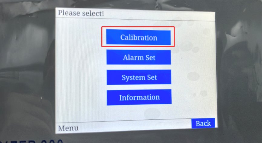
Access the gas analyzer calibration interface:
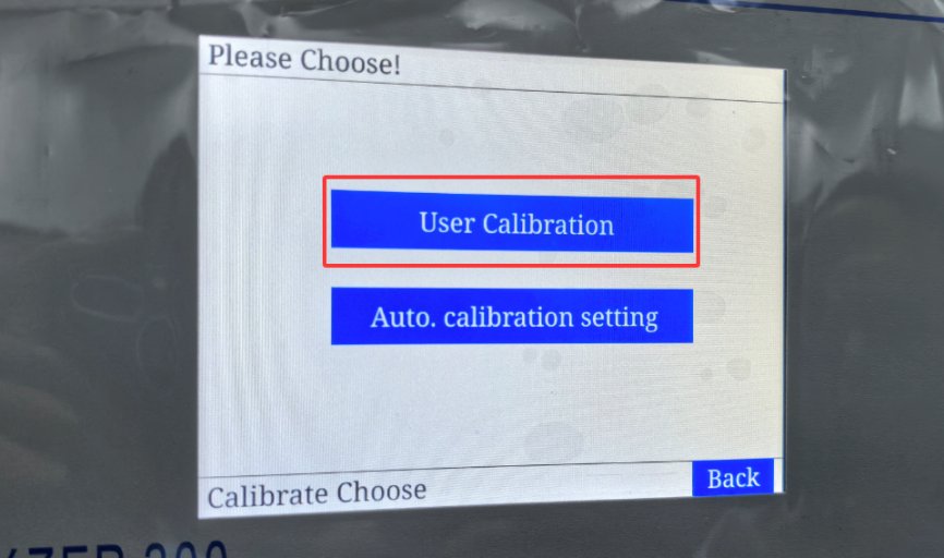
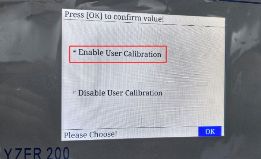
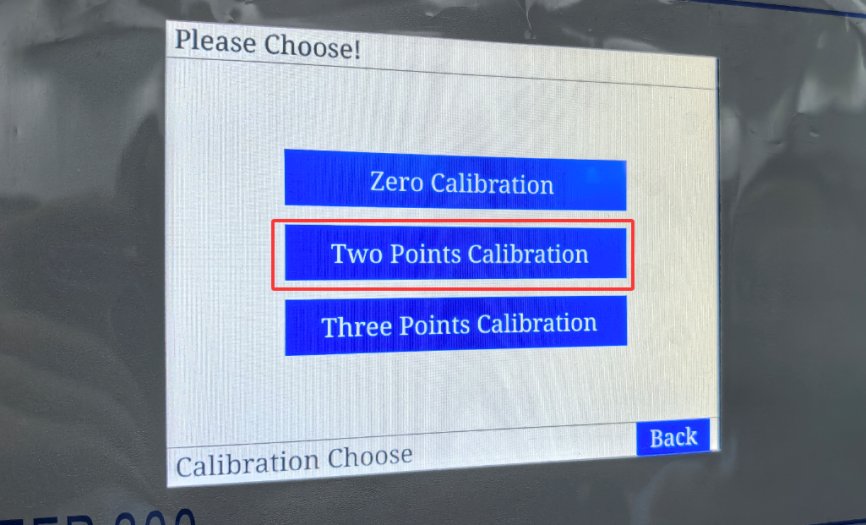
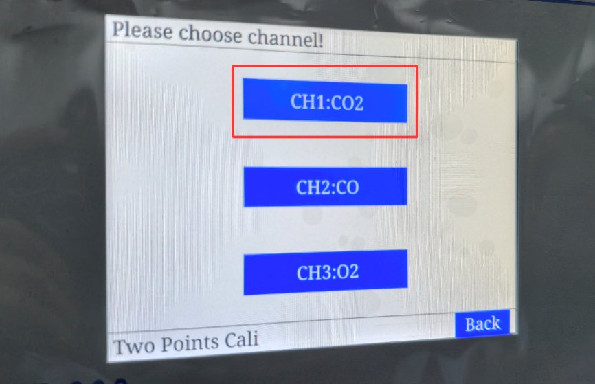
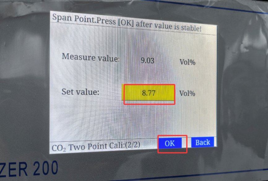
Wait 5 minutes. Once the reading has stabilized, enter 0 and click OK to perform zero calibration.
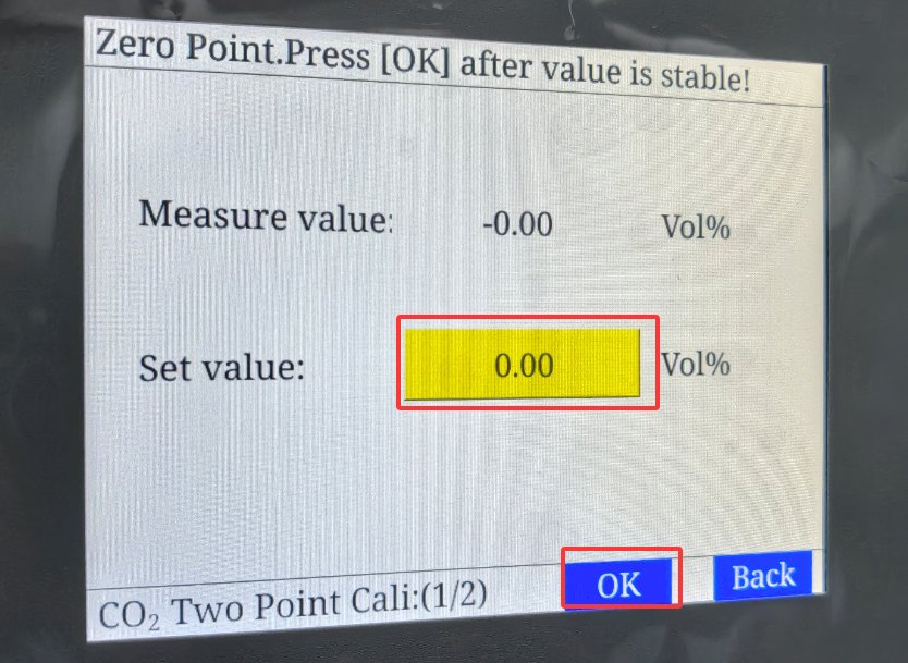
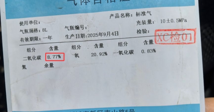
The system will automatically enter the high-point calibration interface. Switch the gas T-joint to the mixed gas cylinder, and slowly adjust the pressure regulator so that the flow rates of the analyzer’s “O₂” and “CO/CO₂” rotameters stabilize at 800–900 cc/min. Wait 5 minutes until the readings stabilize. Then, refer to the mixture composition table for the gas being used, enter the CO₂ concentration, and click OK to complete the high-point calibration.
3.1.2 Calibration of the Zero and Span Points for CO and O₂
Refer to Section 3.1.1; use the same method to calibrate the zero and span points for CO and O2.
Close the calibration gas valve, purge the line with nitrogen for 5 minutes, and complete the calibration. Disconnect the calibration gas supply and set the gas selector switch to “Sample Gas.” (Note: The “Sampling Pump” may only be turned on after the gas selector switch has been set to “Sample Gas.”)
3.2 Calibration of Weighing Equipment (Once a Week)
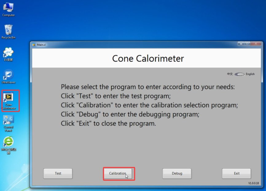
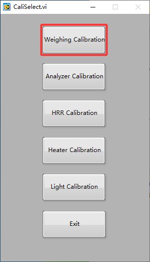
Turn on the power to the test control cabinet and the weighing system switch, then enter the “Weighing Equipment Calibration” screen.
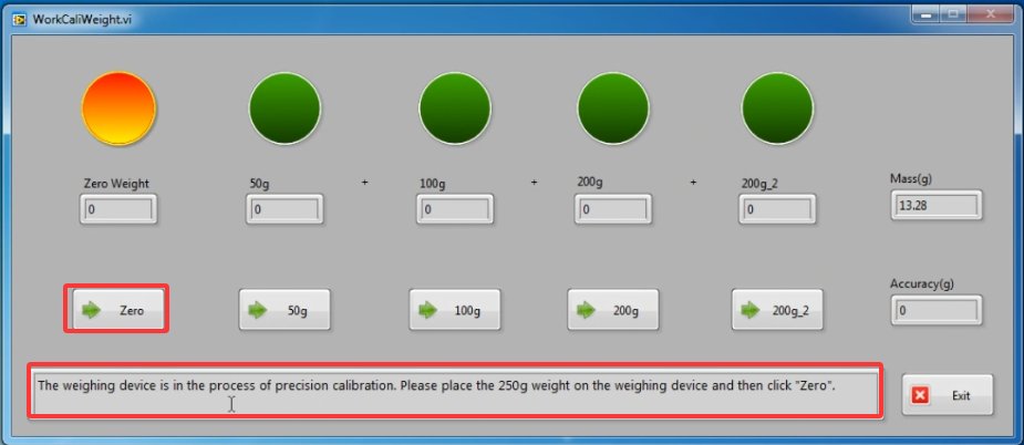
Following the instructions, place the 250g standard weight in the center of the weighing platform, click the “Zero” button in the software, and remove the weight once “0.00g” is displayed.
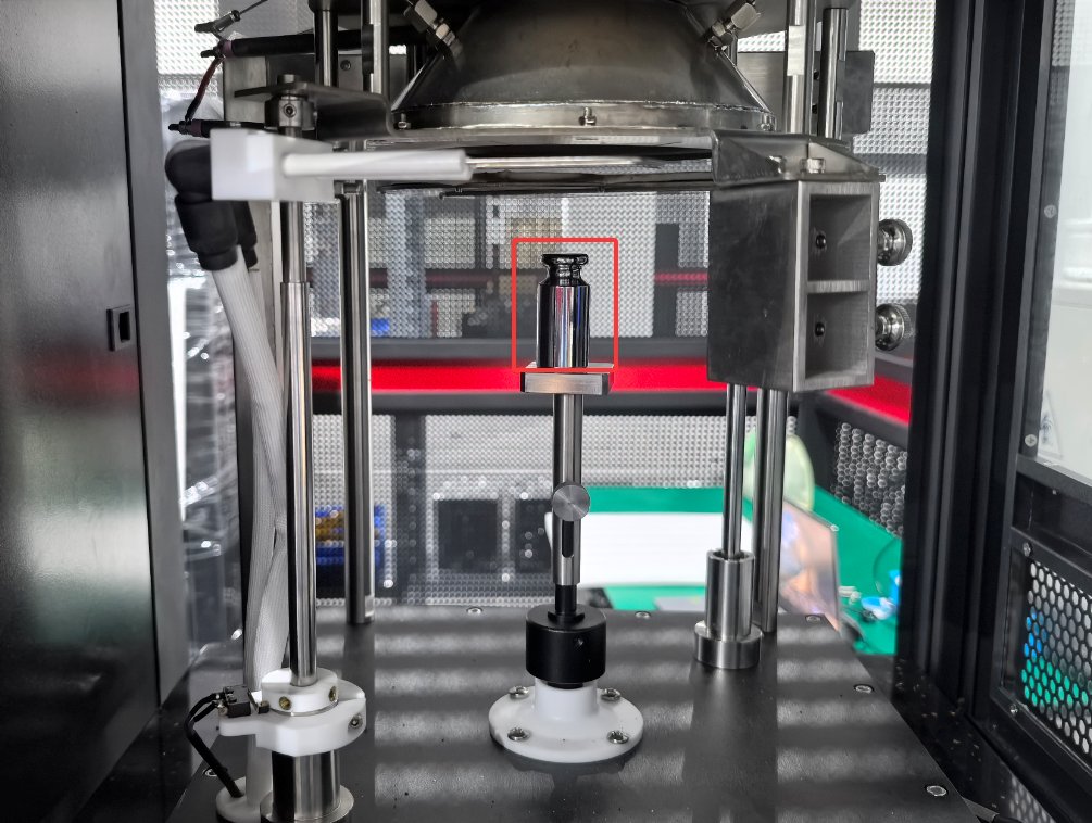
Perform gradient calibration in the following order:
Place the 50g weight on the scale, wait for the reading to stabilize (fluctuation ≤ 0.01g), and click the “50g” button in the software;
Add a 100g weight, and once the weight has stabilized, click the “100g” button;
Add a 200g weight, and once the weight has stabilized, click the “200g” button;
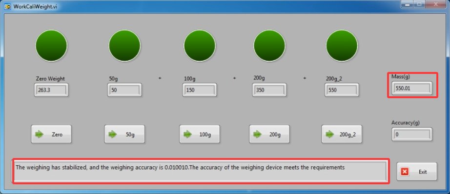
Add the second 200-gram weight (for a total of 400 grams), and once the weight has stabilized, click the “Second 200g” button.
Finally, please note the following: Once the calibration of the weighing equipment is complete, click “Exit” to exit, and remove all weights.
3.3 Calibration of Heat Release Rate (Once a Month)
Preliminary Settings:
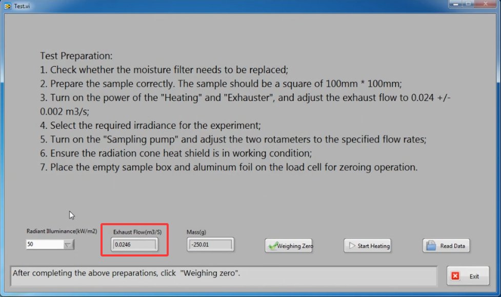
Start the fan and adjust the exhaust flow rate to (0.024 ± 0.002) m³/s;
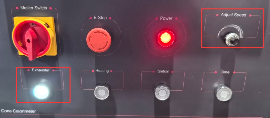
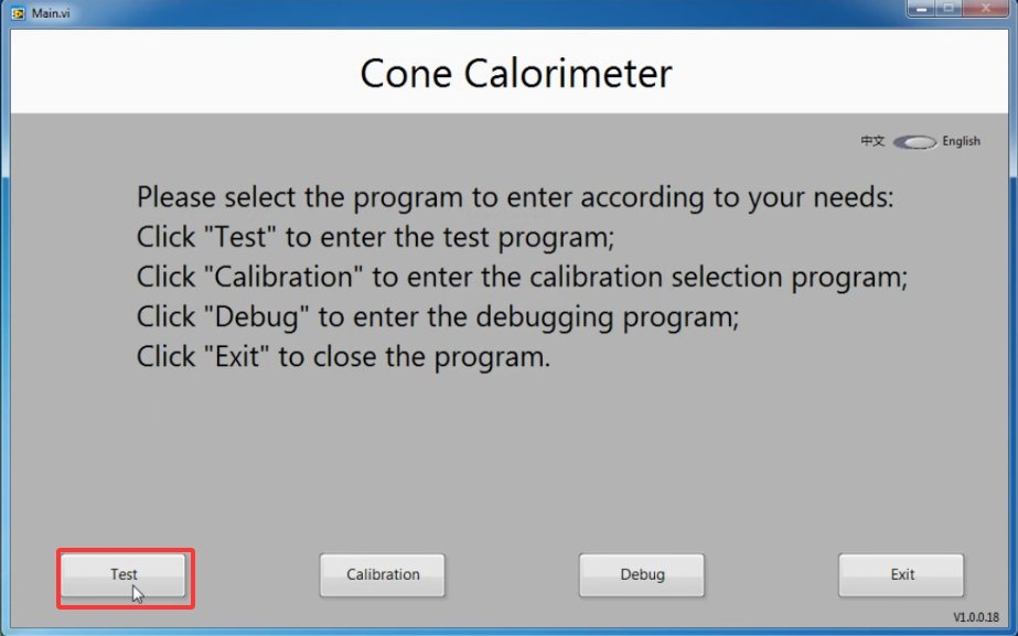
The test interface displays the real-time exhaust flow rate:
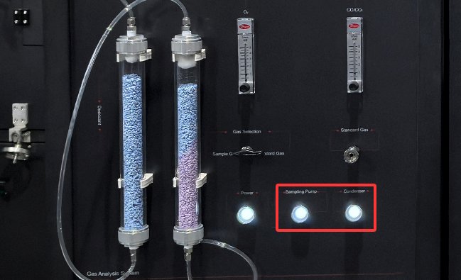
The sampling pump and condenser are still running;
Connect the methane cylinder to the methane connection on the combustion test platform at the rear of the equipment, and adjust the pressure to 0.15 MPa.
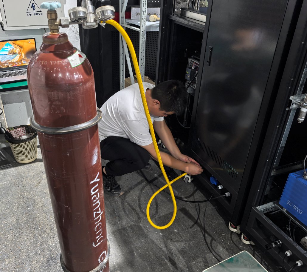
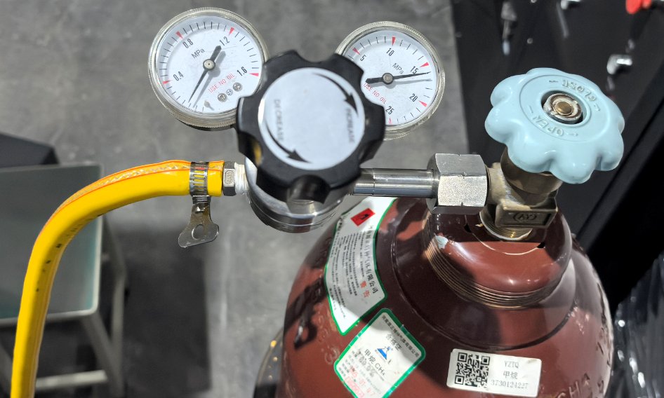
Kalibrasyon prosedürü:
Place the calibrated burner in the second hole at the bottom of the radiation cone, with the combustion orifice facing upward, and ensure it is centered;
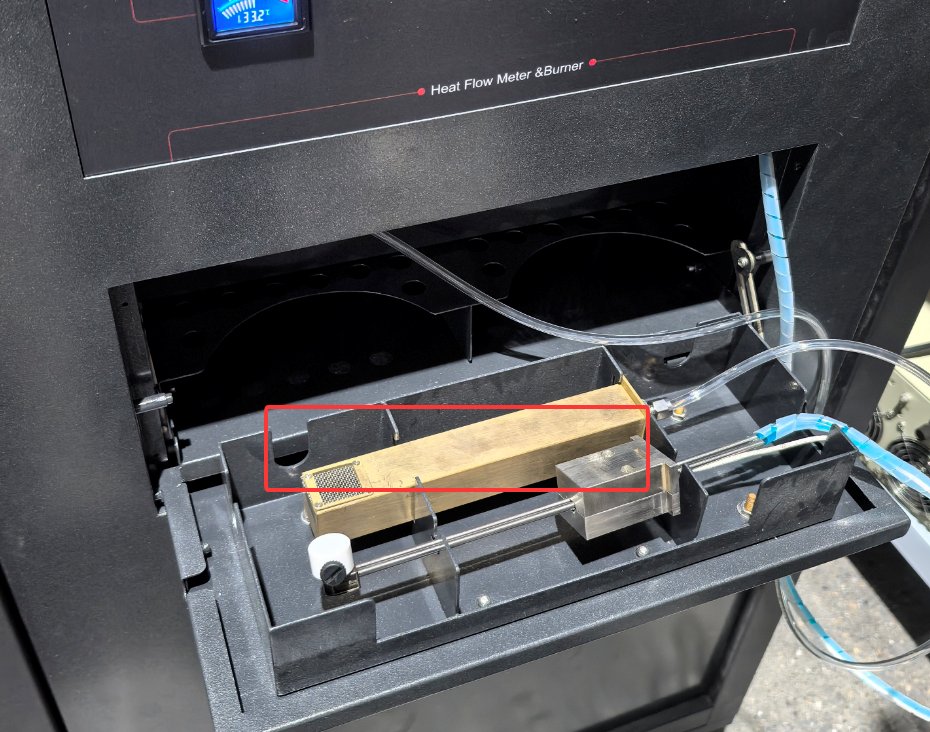
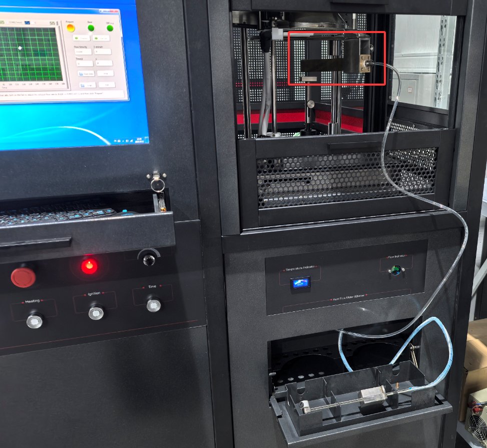
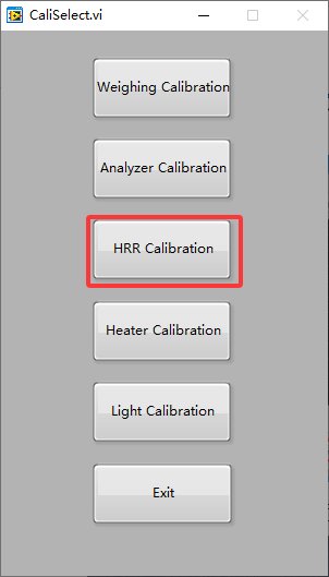
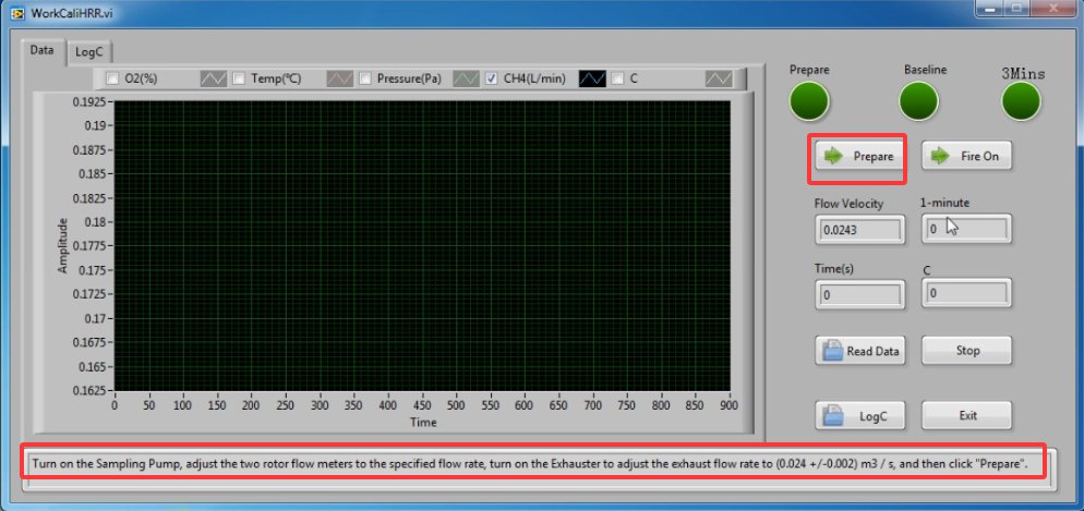
Go to the “Heat Release Rate Calibration” interface in the software, click “Ready,” and the system will automatically collect 1 minute of baseline data;
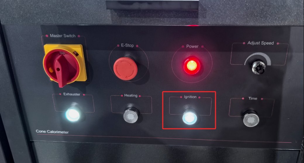
After the baseline acquisition is complete, press the “Ignition” button on the panel,
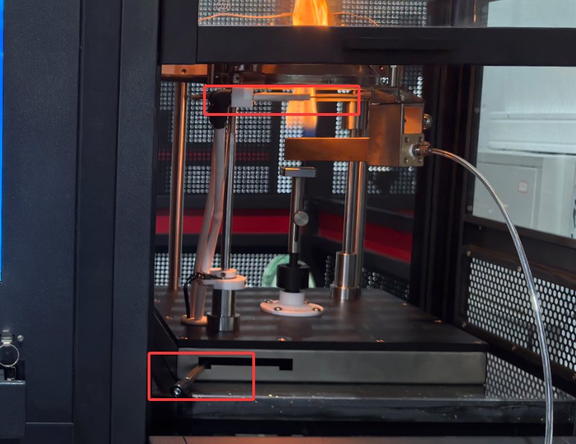
Then immediately move the ignition needle to a position 5 mm above the burner, and once the flame is lit, remove the ignition needle.
Once the flame has stabilized, click “Ignition Complete” in the software;
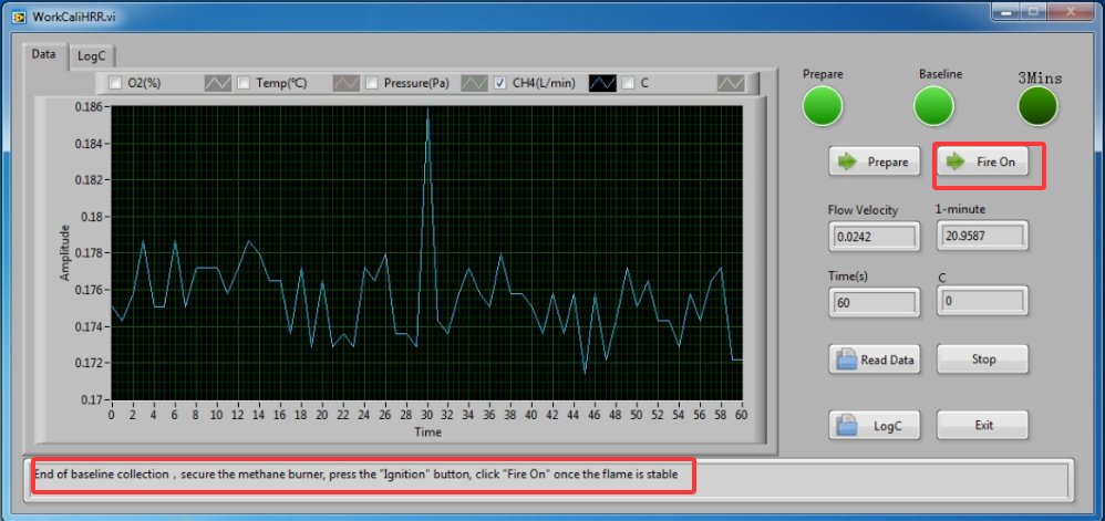
The system continuously records data for 3 minutes and automatically calculates the C-coefficient, with a normal range of 0.038–0.045;
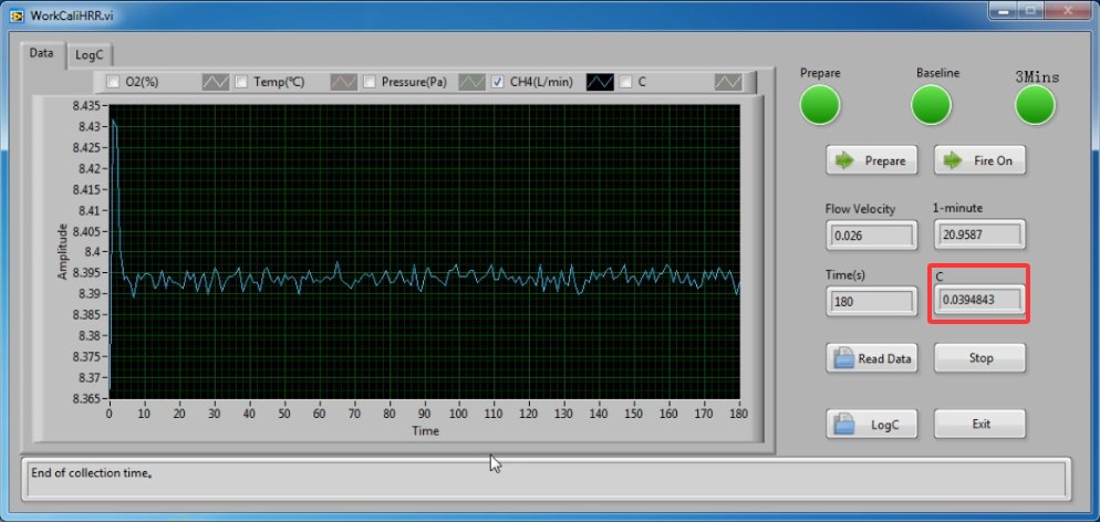
If the C-coefficient is out of range, check whether the methane pressure and exhaust flow rate are normal, and recalibrate.
To complete the operation: Close the valve on the methane cylinder; after the burner flame has gone out, turn off the ignition switch, remove the burner, and purge the methane line for 3 minutes.
3.4 Calibration of the Radiant Cone Heat Flux (Once a Month)
Start the fan and adjust the exhaust flow rate to (0.024 ± 0.002) m³/s; keep the sampling pump and condenser running.
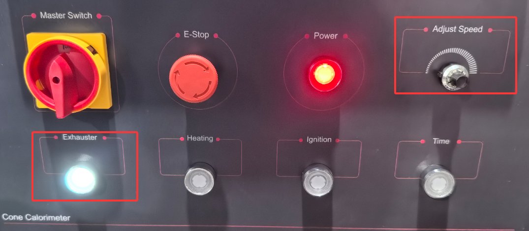
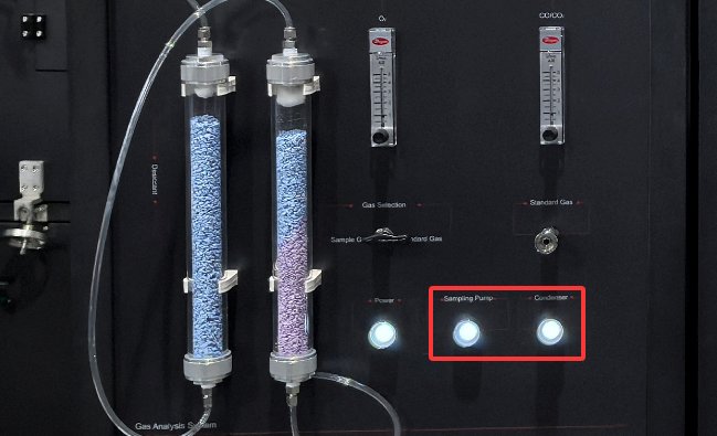
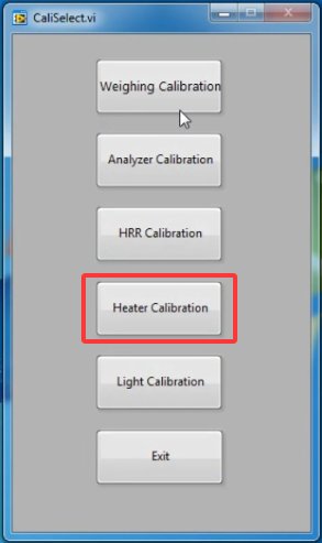
Open the “Radiation Cone Calibration” interface in the software,
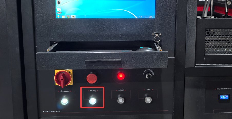
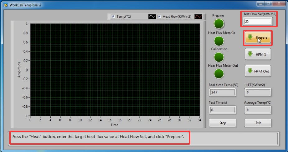
Following the prompts, press the “Heating” button, set the desired target heat flux value (e.g., 25 kW/m², 50 kW/m²), and click “Ready.”
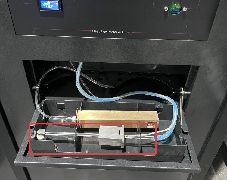
Placing the heat flux meter:
Testing of non-expanding materials: Place the heat flux meter in the first hole at the bottom of the radiation cone;
Expansion Material Test: Place the heat flux meter in the second position.
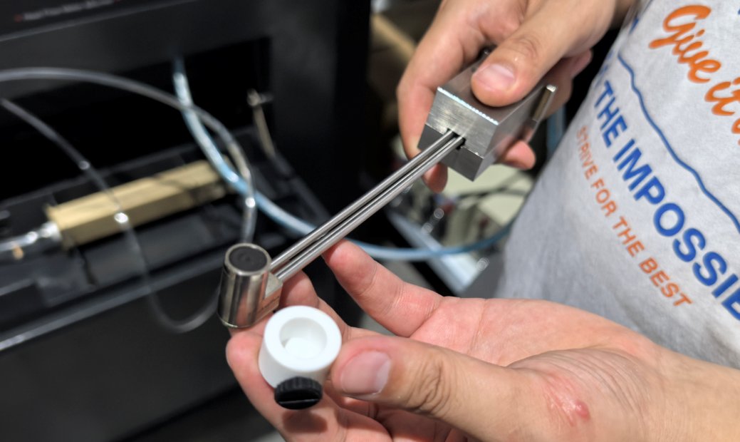
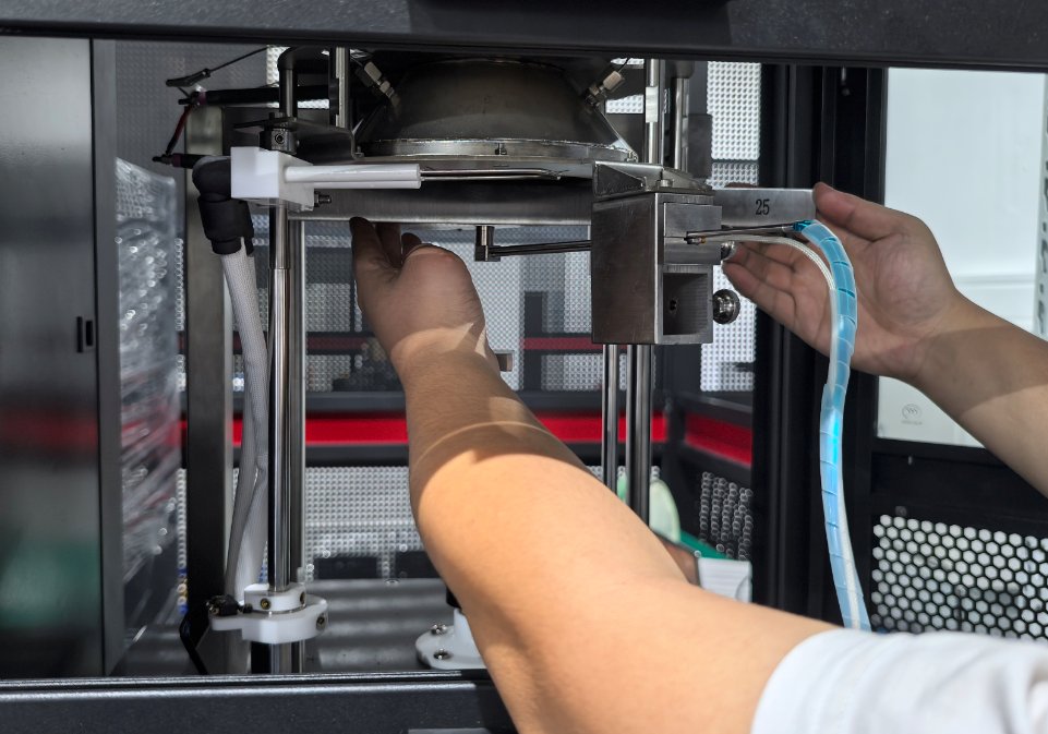
Click the “Insert Heat Flux Meter” button in the software, and the system will automatically heat up to the temperature corresponding to the target heat flux using PID control.
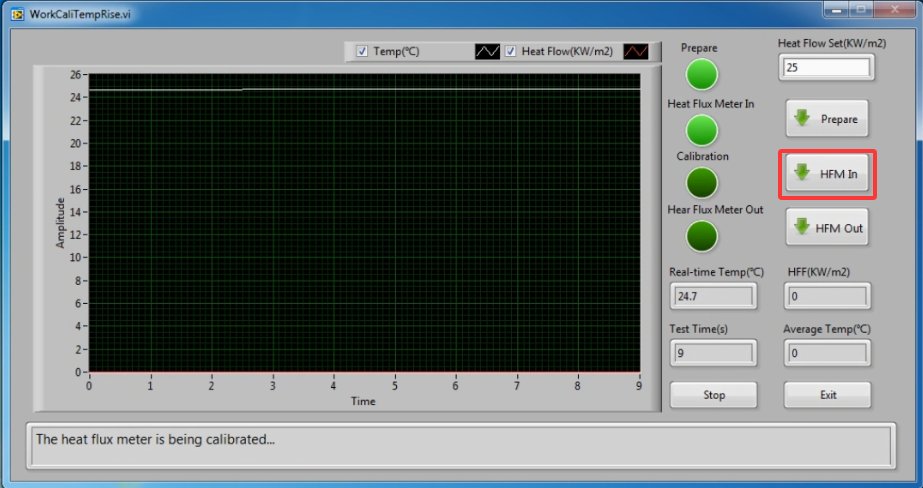
When the software displays the message “Heat flux calibration complete” (heat flux fluctuation ≤ ±1 kW/m², sustained for 1 minute), record the corresponding temperature value; it will be automatically saved to the system’s background.
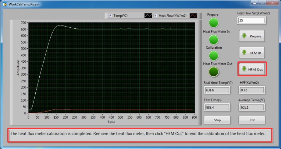
Turn off the heater, wait for the heat flux meter to cool to room temperature, then remove it, and turn off the fan and the sampling pump.
3.5 Calibration of the Optical Path System (Smoke Densitometer) (May be performed before each test)
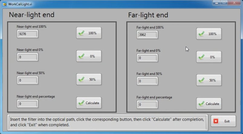
Allow the device to power on for at least 30 minutes to ensure a stable signal between the laser transmitter and receiver, then access the “Optical Path Calibration” interface in the software.
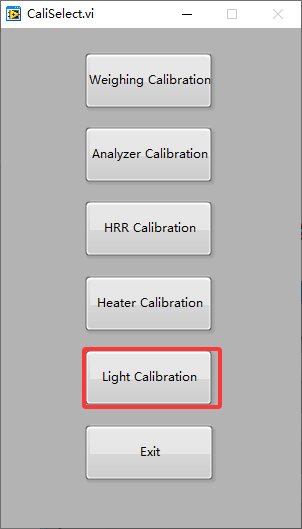
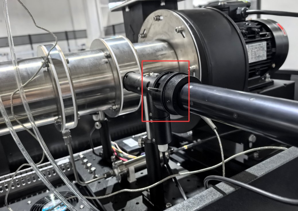
Calibration aperture for the near-end lens of the incident light:
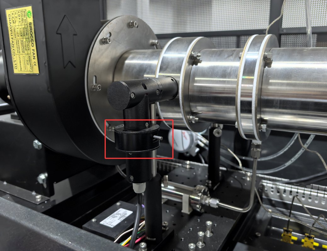
Calibration hole in the high-beam lens of the output light:
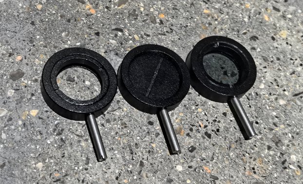
From left to right: 100% light-transmitting sheet, 0% light-transmitting sheet, and 50% light-transmitting sheet.
100% Light Transmittance Calibration: With the light path unobstructed, click the “Incident Light 100%” and “Emergent Light 100%” buttons to record the data (you may click each button up to three times to calculate the average).
0% Light Transmittance Calibration: Place the 0% light transmittance shutters over the incident light and transmitted light calibration apertures, respectively. Click the “Incident Light 0%” and “Transmitted Light 0%” buttons in sequence, and record the data.
50% Transmittance Calibration: Replace the 50% transmittance shading plate, repeat the above steps, and click the “Incident Light 50%” and “Emergent Light 50%” buttons.
Click the “Calculate” button, and the software will automatically generate a transmittance correction factor. Values between 45 and 55 are considered normal, as shown in the figure below; if the value falls outside this range, clean the shading plate and the optical path lenses, then recalibrate.
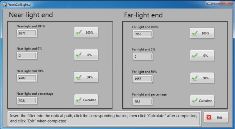
Note: Before starting each test, you must click the “Incident Light 100%” and “Emergent Light 100%” buttons again to recalibrate.
4. Numune Hazırlama ve Kurulum
4.1 Specifications for Sample Preparation
4.1.1 Numune Gereksinimleri
boyutlar: 100 mm × 100 mm square, thickness ≤ 50 mm; the exposed surface must be flush (tolerance ≤ ±1 mm).
Miktar Gereksinimleri: Unless otherwise specified, three parallel samples must be prepared for each irradiation intensity and exposure surface condition to ensure the representativeness of the test specimens.
Kalınlık Gereksinimleri: Test specimens with a thickness of less than 6 mm must be affixed to a backing material so that the total thickness is at least 6 mm. The backing material must not affect the specimen’s fire performance (e.g., an inert material).
4.1.2 State Regulation
In accordance with the ISO 554 standard, the test specimens shall be cured in an environment at (23±2) °C and a relative humidity of (50±5) % until they reach a constant weight.
Constant Weight Test: In two weighings taken 24 hours apart, the difference in mass must be ≤ 0.1% of the specimen’s mass or 0.1 g (whichever is greater).
Special Materials: Materials requiring long-term curing, such as polyamide, must be cured for at least one week in accordance with the GB/T 2918 standard; the curing time must be specified in the test report.
4.1.3 Zeroing the Scale
Place all test accessories—including the sample tray, sample holder, and aluminum foil—on the weighing platform, ensuring they are centered and stable.
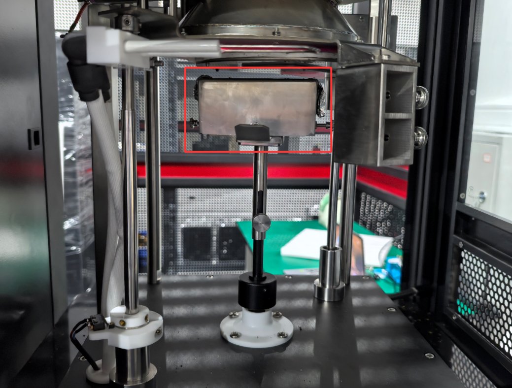
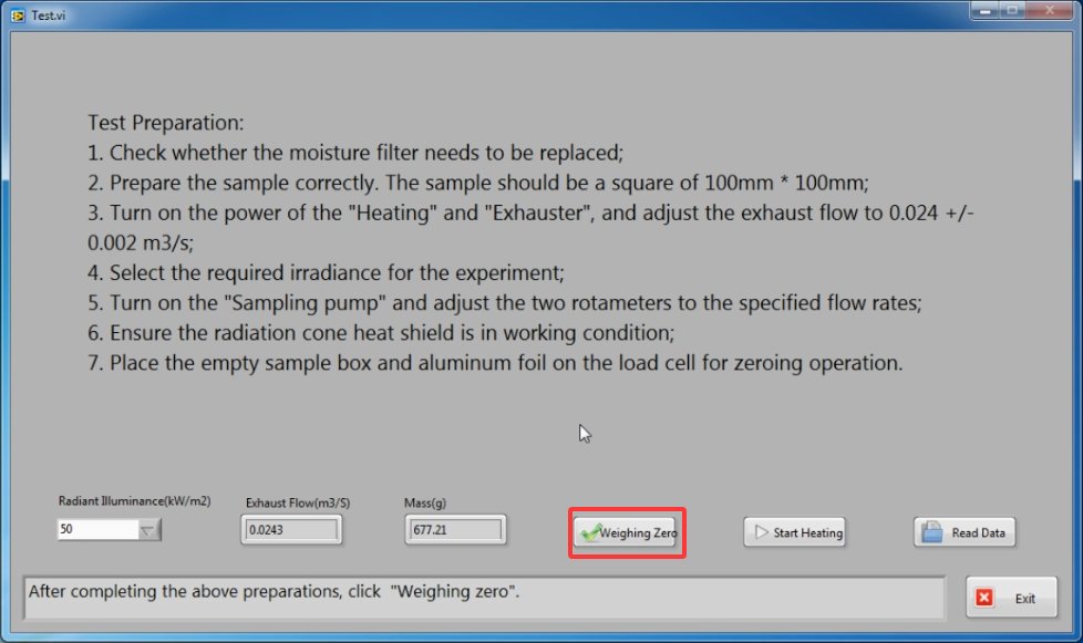
Turn on the weighing system, enter the test interface, click the “Weighing Zero” button in the host computer software, and once “0.00g” is displayed, remove the auxiliary material to prepare for weighing and coating the sample.
4.2 Specimen Encapsulation and Assembly
4.2.1 Specimen Encapsulation
Clean the surface of the specimen with a lint-free cloth dipped in alcohol to remove oil or impurities. After allowing it to air dry, weigh the specimen (to the nearest 0.01 g) and record the weight.
Take a piece of cut-to-size aluminum foil, with the shiny side facing the specimen, and place the specimen in the center of the foil.
Cover the bottom and sides of the specimen, ensuring that the aluminum foil adheres tightly to it. Trim off any excess aluminum foil, leaving it to extend no more than 3 mm beyond the top surface of the specimen (to avoid interfering with radiation exposure).
Preparation of Soft Specimens: Use a pre-made aluminum foil sleeve that matches the thickness of the specimen, then place the actual specimen inside the sleeve, ensuring it is wrapped smoothly.
4.2.2 Installation and Securing
Place the positioning frame upside down on the marble work surface, ensuring the surface is flat and free of debris.
Place the foil-wrapped specimen in the positioning frame with the exposed surface facing down, and adjust its position so that the specimen is centered.
Place a layer of refractory fiber (1–2 layers) on top of the specimen; the fiber layer must extend beyond the edges of the positioning frame to ensure complete coverage of the specimen.
Place the specimen holder on top of the refractory fiber layer, slowly insert it into the positioning frame, and press it down gently to prevent the specimen from shifting.
Securely fasten the positioning frame to the specimen holder with the mounting bolts, ensuring there is no play after assembly; once assembly is complete, the aluminum foil should not be visible; if it is, readjust the assembly.
5. Key Test Procedures
5.1 System Startup and Parameter Configuration
5.1.1 Başlatma Prosedürü
Turn on the power to the standard gas analysis cabinet, start the gas analyzer (which has been preheated for 24 hours), the sampling pump, and the condenser (set to 4°C).
Turn on the main power supply to the test control cabinet, start the fan, and adjust the speed control knob to stabilize the exhaust flow rate at (0.024 ± 0.002) m³/s.
Press the radiation cone heating button to apply the calibrated heat flux value (e.g., 25 kW/m²), then click “Start heating,” and the system will automatically heat up to the target temperature.
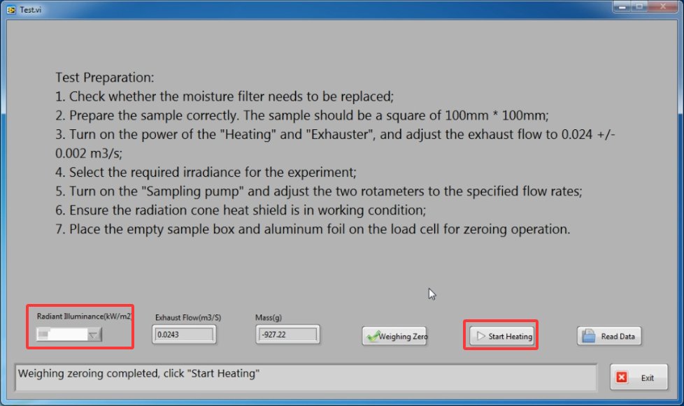
5.1.2 Parameter Adjustment
Egzoz Akış Hızı: Monitor the pressure differential across the orifice plate flowmeter and adjust the fan speed control knob in real time to ensure that flow rate fluctuations do not exceed ±0.001 m³/s.
Radiation cone distance: Adjust the height of the radiation cone so that the distance between its lower surface and the upper surface of the specimen meets the test requirements (typically 25 mm, which can be set in the software), with a deviation of ≤±1 mm.
Veri toplama aralığı: The default setting is 3–5 seconds; for specimens with an expected combustion time of less than 5 minutes, this interval may be reduced to 1 second (requires manual adjustment in the software).
Test süresi: The default setting is 32 minutes (including a 30-minute burn test and 2 minutes of additional data collection). This can be adjusted based on the characteristics of the test specimen, but the minimum duration must be at least 5 minutes.
5.2 Conducting the Test Procedure
5.2.1 Sample Placement and Baseline Acquisition
Place a thermal barrier (consisting of a hollow mounting frame lined with heat-resistant fiber padding) on the weighing platform to prevent radiant heat from affecting weighing accuracy.
Following the software prompts, once heating is complete, place the sample inside and use the handle to move the radiation shielding layer over the sample,
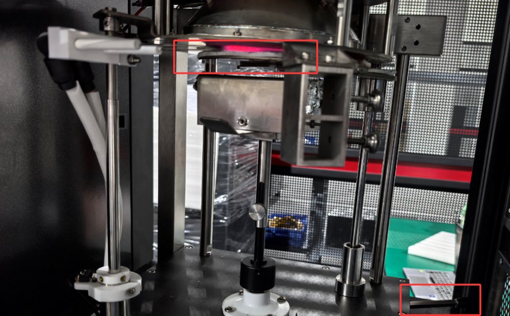
Click “Start Baseline Collection” and continue collecting data for 1 minute.
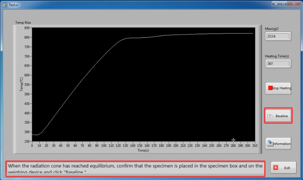
Baseline data must meet the following criteria: oxygen concentration close to 21%, heat flux fluctuations ≤ ±1 kW/m², and stable weight readings. Otherwise, troubleshoot the equipment and collect the data again.
5.2.3 Ignition and Monitoring
Once the baseline data has been collected, follow the prompts to remove the radiation shielding and click “Start Test.”
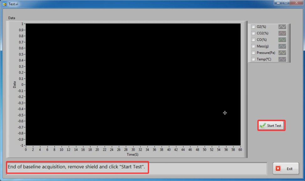
Press the “Ignition” button and, within 1 second, move the ignition needle to a position 5 mm above the sample surface to ignite it. When the sample ignites, press the “Time” button to record the ignition time; after it goes out, press the “Time” button again to record the extinguishing time. If the sample ignites multiple times, press the button each time to record the times.
Carefully observe the combustion behavior of the specimen and record the following times:
Flash-over time: The moment when a flame lasts for < 1 s;
Short burn time: The duration of the flame is 1–10 seconds;
Ignition time: The moment when a flame that lasts for more than 10 seconds appears.
Immediately remove the ignition needle after ignition; if the flame goes out, reposition the ignition needle over the sample within 15 seconds and maintain ignition until the end of the test, while recording this anomaly in the software.
During the test, record changes in the specimen’s appearance (such as melting, swelling, bursting, or dripping) every 5 minutes, and monitor the data curves (heat release rate, mass loss, etc.) in real time. If any abnormal fluctuations occur, note the cause.
5.3 Test Termination and Shutdown
5.3.1 Fesih Koşulları
The software automatically stops data collection when any of the following conditions are met (it can also be stopped manually, but the reason must be recorded):
After 32 minutes of continuous burning (the system automatically shuts down);
The specimen did not ignite within 30 minutes (it must be confirmed that there was no peak in the heat release rate);
The oxygen concentration returns to within 0.01% of the pre-test concentration and remains at that level for 10 minutes;
The mass of the sample decreased to 0 g (complete combustion).
Note: Under no circumstances may the test duration be less than 5 minutes; otherwise, the data will be invalid.
5.3.2 Kapatma Prosedürü
Click “End Test” in the software to save the test data and generate the raw curve.
Turn off the radiant cone heater switch and wait until the radiant cone temperature drops below 200°C before proceeding with the next steps.
Remove the specimen holder (if any molten residue remains, allow it to cool before cleaning it off), and replace the insulation layer on the weighing platform.
Turn off the power to the igniter, the optical system, and the weighing system.
Continue running the blower and the sampling pump for 30 minutes to purge any residual flue gas from the piping, then shut off the blower and the sampling pump.
Turn off the condenser and the gas analyzer, and finally turn off the main power supply to the standard gas analysis cabinet and the test control cabinet.
Clean up the test platform and dispose of any test specimen residue in accordance with hazardous waste regulations.
6. Data Processing and Reporting
6.1 Data Validity Check
6.1.1 Parallel Sampling Verification
Calculate the “average heat release rate within 180 seconds after ignition” for the three parallel specimens. If the deviation of any single specimen from the average is ≤10%, the data is considered valid, and the arithmetic mean of the three specimens is taken as the result.
If the deviation exceeds 10%, take an additional 3 test specimens and retest them; report the arithmetic mean of the 6 test specimens in the final report, and note the anomalous results of the initial test specimens.
6.1.2 Sorun Giderme
Test data is invalid and must be retested under the following circumstances:
The specimen melted and overflowed from the specimen holder, resulting in inaccurate measurements of mass loss;
The specimen bursts apart or expands excessively, coming into contact with the igniter or the lower surface of the radiation cone;
Failures in equipment such as gas analyzers and weighing systems (e.g., data drift exceeding standards);
During the test, fluctuations in the exhaust flow rate exceeded ±0.002 m³/s.
6.2 Calculation of Key Parameters
6.2.1 Heat Release Rate (HRR)
Calculate the average and peak values using the trapezoidal integration method:
Determining the Initial Value of the Integral: Use the heat release rate value closest to the ignition time, or the first reading following the last negative value.
Calculating the 180s Average (using a 5s sampling interval as an example):
The 35 data points collected after the initial sum (totaling 180 seconds);
Calculate “1/2 of the initial value + 1/2 of the value from the 36th data point”;
Total score = the sum of the two items above × 5 seconds; average = total score ÷ 180 seconds.
zirve: The maximum value on the post-combustion heat release rate curve, accurate to 0.1 kW/m².
6.2.2 Parameters Related to Mass Loss
Mass loss (ML): The difference between the initial mass and the mass remaining after the test, expressed in g/m² (mass loss divided by the sample area).
Average Mass Loss Rate (MLR):
Standard calculation: Mass loss ÷ (End time of test – Ignition time), in g/(m²・s);
Calculation of Characteristics: Use data from the period during which mass loss ranges from 10% to 90%, and calculate according to the formula above.
6.2.3 Other Parameters
Toplam Isı Salınımı (THR): The trapezoidal integral of the heat release rate over the entire test period, in MJ/m².
C – Coefficient: Use the calculated value from the heat release rate calibration, rounded to 4 decimal places.
Duman Yoğunluğu: Calculated based on the light transmittance measured by the optical system, combined with the exhaust airflow rate; unit: m²/m².
6.3 Presentation of Test Reports
6.3.1 Temel Bilgiler
The report must include the following key elements:
Laboratory name, address, and test date;
Name and address of the client, manufacturer, and/or supplier;
Tester, trade name of the test specimen, identification code, composition, and color;
Specimen specifications: thickness (mm), mass (g), density (kg/m³) (for composite materials, specify the parameters of each component);
Test Conditions: Irradiance (kW/m²), exhaust airflow (m³/s), C-coefficient, specimen mounting method;
Number of parallel samples and results of the validity assessment.
7. Routine Maintenance and Emergency Response
7.1 Rutin Bakım Prosedürleri
7.1.1 Immediate Maintenance (After Each Test)
Cold Trap / Condenser: Drain all condensed water from the interior and check that the drain is unobstructed; if blocked, blow it out with compressed air.
Kurutucu: Check the anhydrous calcium sulfate inside the standard gas analysis cabinet; if it has changed from blue to pink, replace it immediately. When replacing it, shut off the sampling pump to prevent air from entering the tubing.
Cleaning of Test Specimen Residue: Use specialized tools to clean residue from the combustion test platform, the smoke collection hood, and the exhaust duct. Do not rinse high-temperature components directly with water.
Piping Inspection: Check the gas sampling lines for kinks or leaks and ensure that all connections are secure. If any issues are found, tighten or replace them immediately.
7.1.2 Düzenli Bakım (Ayda Bir Kez)
Equipment Calibration Review: Recalibrate the gas analyzer’s zero point, the weighing equipment, and the optical path to ensure accuracy meets requirements.
Piping Purge: Before switching to a different gas, purge the piping with nitrogen for 5–10 minutes to remove any residual gas and prevent mixed reactions.
Elektrik Sistemi Muayenesi: Check that the power cords and ground wires are in good condition, and verify that all buttons and switches are responsive and make good contact.
Soğutma Sistemi Bakımı: Replace the condenser coolant (once a year), check the water level in the portable water cooling system, and top off with distilled water (do not use tap water).
Accessory Calibration: Standard weights and light-shielding plates are provided to ensure that the accuracy of the calibration accessories meets the required standards.
7.2 Yaygın Sorunların Giderilmesi
|
Arıza Belirtileri |
Olası Nedenler |
Bertaraf Yöntemleri |
|
Igniter has no high-voltage ignition |
1. Loose or damaged high-voltage leads; 2. Incorrect gap between the ignition needle and the nozzle (should be 3–5 mm); 3. Igniter power supply failure |
1. Retighten or replace the high-voltage leads; 2. Use a caliper to adjust the spacing to 3–5 mm; 3. Contact a professional to repair the power supply. |
|
Significant Data Drift in the Gas Analyzer |
1. The desiccant has expired; 2. A leak in the tubing; 3. The analyzer has not been sufficiently preheated |
1. Replace the anhydrous calcium sulfate; 2. Perform a nitrogen leak test and tighten the joints; 3. Ensure the preheating time is ≥24 hours |
|
Unstable weighing data |
1. The weighing platform is vibrating; 2. The thermal insulation layer is missing or has failed; 3. The specimen mounting bracket is loose |
1. Eliminate sources of environmental vibration; 2. Reinstall the insulation; 3. Tighten the mounting bracket bolts |
|
Abnormal heat release rate curve (no peak) |
1. Radiant heat flux did not meet the standard; 2. Significant deviation in exhaust gas flow rate; 3. The test specimen did not ignite |
1. Recalibrate the radiant cone heat flux; 2. Adjust the fan flow rate to the standard range; 3. Check the igniter or increase the radiant irradiance |
|
The condenser is not cooling |
1. Low coolant level; 2. Diaphragm pump failure; 3. Temperature controller malfunction |
1. Top off the coolant; 2. Inspect the pump housing’s power supply and impeller, and replace any damaged parts; 3. Calibrate or replace the temperature controller |
7.3 Safety and Emergency Measures
7.3.1 Gas Leak Emergency Response
Immediately close the main valve on the methane cylinder, press the “Emergency Stop” button on the test control cabinet, and cut off the power to the equipment.
Do not use any open flames (such as lighters or alcohol lamps) or electrical equipment (such as exhaust fans or lighting) to prevent electrical sparks from igniting the gas.
Open all doors and windows in the laboratory to maintain natural ventilation and accelerate the dispersion of the gas; if the leak is significant, evacuate the laboratory immediately and call the fire department.
Once the gas odor has dissipated, use soapy water to check for leaks (paying special attention to the cylinder connections and pipe joints). Only after replacing any damaged O-rings or pipes should you resume use.
7.3.2 Emergency Response to High-Temperature Burns
If your skin comes into contact with high-temperature components (such as the radiation cone or the specimen mounting frame), immediately rinse the burned area with running cold water for 15–20 minutes to lower the skin temperature.
If blisters form on the burned area, do not pop them yourself; cover the area with sterile gauze and seek medical attention immediately.
If molten material splashes into the eyes, immediately rinse them with an eyewash station for 10 minutes (keeping the eyelids open), avoid rubbing the eyes, and then seek medical attention.
7.3.3 Emergency Procedures for Equipment Overload
If the equipment emits unusual noises, smoke, or strange odors, immediately press the “Emergency Stop” button to cut off the main power supply.
After the equipment has cooled down, check the electrical system (such as wiring, contactors, and motors) for overload damage. Do not restart the equipment until the fault has been diagnosed and resolved.
Electrical malfunctions must be repaired by qualified electricians; under no circumstances should you attempt to disassemble the equipment yourself.