
 İngilizce
 中文简体
中文简体 Русский
 Español
 Português
 Türkçe
 العربية
 Deutsch
 Polski
 Italiano
 Français
 한국어
한국어 ไทย
ไทย Tiếng Việt
 日本語
日本語





























UV Yaşlanma Test Odası
Kullanım Kılavuzu
uygulanabilir LISUN modeller: UV-263LS
1. Kutudan Çıkarma ve Ekipmanları Tanıma
1.1 Temel Teknik Özellikler
| LISUN Model | UV-263LV | UV-263LS | UV-263LT |
| Muhafaza Yapısı | Trapezoidal İç Oda | Square Inner Container | Masaüstü Muhafazası |
| Inner Chamber Dimensions (W x D x H) | 450 × 1140 × 500 mm | 550 × 1140 × 450 mm | 500 × 400 × 400 mm |
| Dış Kutu Boyutları (G x D x Y) | 600 × 1325 × 1500 mm | 650 × 1300 × 1750 mm | 930 × 460 × 630 mm |
| Sıcaklık aralığı | Oda sıcaklığı + 10°C ila 70°C | ||
| nem Aralığı | ≥75% bağıl nem | ||
| Kontrol Sistemi | LCD programlanabilir kontrol ünitesi, UV ışınlarına maruz kalmayı, yüksek sıcaklıkları, yüksek nemi, yağmuru, yoğuşmayı, karanlığı ve diğer koşulları simüle eder. | ||
| UV Lamba Özellikleri | 8 adet US ATLAS floresan lamba, 1200 mm uzunluğunda, her biri 40 W gücünde, lamba başına 1000 saat kullanım ömrüne sahip. | Çin'de üretilmiştir, ampul başına 20W, toplam 3 ampul. | |
| Wavelength Range of UV Lamps | Standard UVA-340 lamp: Wavelength range 315–400 nm, peak wavelength 340 nm (Optional UVB-313 lamp: Wavelength range 280–315 nm, peak wavelength 313 nm; Additionally, a UVA-351 lamp is available as an option: wavelength range 315–400 nm, peak wavelength 351 nm) | Standard UVA-340C lamp: Wavelength range 315–400 nm, with a peak wavelength of 340 nm (UVB-313C available as an option) | |
| Işınlama şiddeti | 0.35–1.2 W/m², adjustable (with built-in irradiance meter) | ||
| Işınlanmış kara tahtanın sıcaklığı | 50 ° C – 70 ° C | ||
| Numune Boyutları | 48 adet, 70 × 150 mm | Irregular specimens | 18 adet, 70 × 150 mm |
| Su Kaynakları ve Tüketimi | 8 to 10 liters of purified water or distilled water per day (to be provided by the customer) | ||
1.2 Kutunun Açılması ve İçeriğin Kontrol Edilmesi
1.2.1 Ambalajdan Çıkarma ve Görsel İnceleme
When unpacking the equipment, handle it gently to avoid scratching the exterior casing with sharp tools. After unpacking, first inspect the exterior of the main unit to ensure there is no visible deformation, dents, or peeling paint, and that the panel instruments and buttons are not damaged or loose. If you discover any damage or deformation to the equipment or accessories, do not power it on. Contact LISUN hemen müşteri hizmetleri.
1.2.2 Ana Ünite ve Aksesuarlar
UV aging test Chamber (main unit): 1 unit.
Unless otherwise specified, this equipment does not include any other accessories.
Download links for the electronic user manual, warranty card, and other documents have been sent via email. Please download them as soon as possible. If you missed the email, please feel free to contact us to request the download links again.
1.3 Ekipman Yapısının Tanımı
1.3.1 Front and Right Side of the Test Chamber
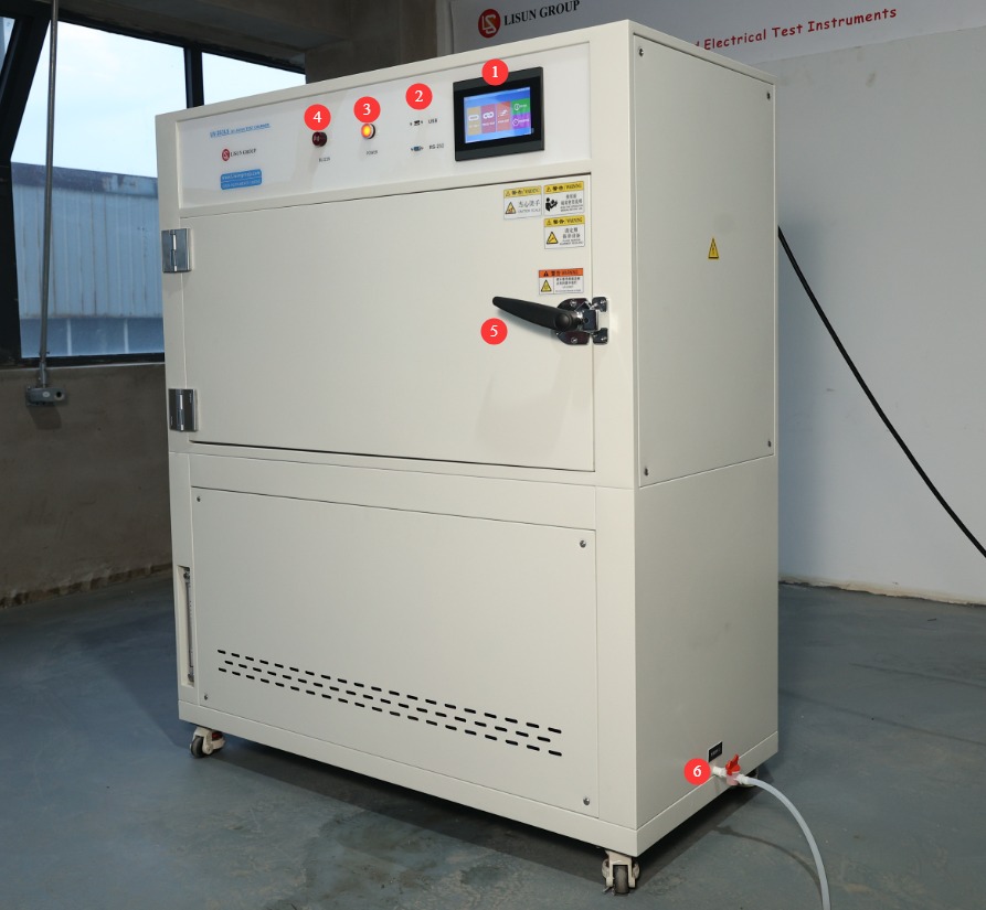
① Touchscreen; ② USB port for software updates or exporting test curves; RS-232 port (for backup); ③ Power switch; ④ Alarm—sounds when the device detects an abnormality, such as a lack of water; ⑤ Test chamber door; ⑥ Drain valve—open only when draining the water tank is necessary.
Şekil 1
1.3.2 Left Side of the Test Chamber
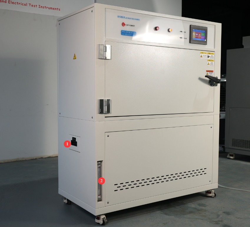
① Water-filling drawer; ② Water level viewing window.
Şekil 2
1.3.3 Test Odasının İç Yapısı
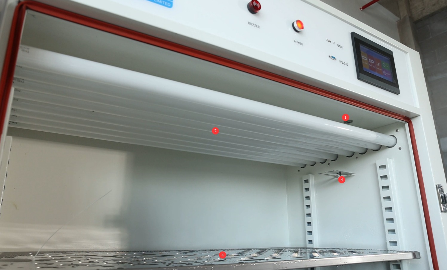
① Optical Fiber; ② UV lamp; ③ Blackboard temperature probe and test chamber temperature probe; ④ Sample rack.
Şekil 3
2. Güvenlik Önlemleri
2.1 Elektriksel Güvenlik
2.1.1 Güç Bağlantısı
220V single-phase power; power outlets must comply with safety standards, be properly grounded, and have a rated current that matches the equipment’s power rating (it is recommended to install a dedicated circuit breaker).
2.1.2 Topraklama Özellikleri
The equipment must be reliably grounded, with a grounding resistance of ≤50 Ω. Do not use gas pipes, non-metallic water pipes, or the neutral wire as a substitute for the ground wire. After grounding is complete, use a Grounding Resistance Tester to measure the grounding resistance. Power may only be applied after confirming that it meets the requirements, to prevent electric shock, equipment malfunctions, or measurement errors caused by poor grounding.
2.1.3 İşlem İçin Kontrendikasyonlar
Before wiring, inspecting, or maintaining the equipment, you must turn off the circuit breaker on the back of the equipment and disconnect the main power supply. Only proceed after confirming that there is no residual voltage;
Elektrik çarpması riskini önlemek için cihazın güç düğmesini, dokunmatik ekranını veya düğmelerini ıslak ellerle kullanmayın;
Toz veya yabancı cisimlerin kısa devreye neden olmasını veya bileşenlere zarar vermesini önlemek için elektrik kontrol panosunun içine herhangi bir yabancı cisim (alet veya kağıt gibi) koymayın;
Kontrol ünitesine veya elektrikli bileşenlere zarar verebilecek kısa devreleri önlemek için, ekipman çalışırken güç kablolarını veya sinyal kablolarını takıp çıkarmayın.
2.2 Operasyonel Güvenlik
2.2.1 Test Numunesi Gereksinimleri
The equipment must not be used for testing flammable, explosive, toxic, or highly corrosive substances (such as alcohol, gasoline, strong acids, strong alkalis, etc.). Since the equipment is not equipped with explosion-proof devices, such substances may cause fires, explosions, or corrosion of the equipment;
The sample volume must not exceed 80% of the basket’s capacity, and the weight must not exceed the equipment’s specified load capacity (shelf load capacity ≤ 20 kg).
2.2.2 Operasyonel Güvenlik
Ekipman çalışır durumdayken, profesyonel olmayan kişilerin ekipmanı sökmesi veya onarması yasaktır. Arıza durumunda, satış sonrası servis personeliyle iletişime geçin veya ekipmanı bir teknisyenin gözetiminde çalıştırın;
Do not open the chamber door during the test. The lamps emit intense ultraviolet radiation when in operation, which may cause severe sunburn or eye inflammation (similar to “snow blindness”);
Cihaz için belirtilen aralığın ötesinde bir sıcaklık ayarlamayın;
When placing samples, distribute them evenly on the shelves; do not overcrowd them. Leave at least one-third of the space empty to ensure proper circulation of hot air inside the chamber and prevent localized temperature variations;
If the equipment triggers an alarm, immediately stop the test and troubleshoot the problem (see “Chapter 7: Troubleshooting and Resolution of Common Problems”). Do not force the equipment to restart; operating it before the problem is resolved may cause further damage to the equipment.
2.2.3 Yasaklanmış Davranışlar
Elektrik çarpmasına neden olabilecek iç yüksek voltajlı bileşenlere dokunmaktan kaçınmak için, ekipman çalışırken kontrol paneli kapağını açmayın;
Do not disassemble core components such as temperature sensors and heating elements without authorization. Modifying the equipment will void the warranty and may lead to safety incidents;
Do not place heavy objects (such as tools or accessories) on top of the equipment to avoid damaging the equipment panel or interfering with heat dissipation;
Ekipmanların etrafına yanıcı maddeler (karton kutular, plastik ambalaj vb.) yığmayın.
2.3 Çevresel Güvenlik
2.3.1 Kurulum Gereksinimleri
The equipment must be installed in an air-conditioned room where the ambient temperature is maintained between 5°C and 25°C and the relative humidity is ≤85%. If the ambient humidity is high, condensation may form near the equipment door and test ports; in such cases, increase ventilation in the room or use a dehumidifier;
The installation site must be free of high concentrations of dust, corrosive gases (such as sulfur dioxide and chlorine), and flammable or explosive atmospheres. Direct sunlight must not shine on the equipment to prevent corrosion of the equipment housing and deterioration of electrical components;
Keep the device away from locations where ambient temperature fluctuates significantly, such as near vents or doorways, to prevent the device’s temperature control accuracy from being affected.
2.3.2 Alan Gereksinimleri
The distance between the equipment enclosure and the wall, as well as surrounding structures (such as other test equipment and shelving), must be at least 1500 mm to ensure unobstructed ventilation at the equipment’s heat vents (rear and sides);
Numune yerleştirme ve çıkarma işlemlerini kolaylaştırmak için, ekipman kapısı açıklığında en az 2000 mm boşluk bırakılmalıdır; bu boşluk kapının her yöne açılabilmesini sağlar.
2.3.3 Yatay Yerleştirme
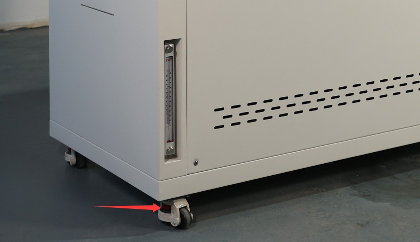
The equipment must be placed on a level surface. Use a spirit level to ensure the equipment is level: Place the spirit level on the top surface of the equipment and confirm that the bubble is centered. Note: The following types of legs are adjustable to ensure the test chamber is level.
Şekil 4
Cihazın eğimli olması, hazne içindeki sıcaklık dağılımının dengesiz olmasına ve kapı sızdırmazlığının bozulmasına neden olabilir; bu da test sonuçlarını ve cihazın kullanım ömrünü etkileyebilir.
2.4 Diğer
Bu kılavuzda yer almayan konular için lütfen dikkatli ilerleyin veya bizimle iletişime geçin.
3. Sınav Öncesi Hazırlıklar
3.1 Su Deposunun Doldurulması
Open the machine’s water drawer and check inside the drawer and the water tank (to check the water tank, you’ll need to open the bottom panel on the front of the machine) for any debris or standing water (clean the inside of the water tank before using the machine for the first time).
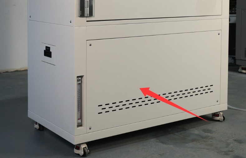
Şekil 5
Before adding water, check whether the drain valve on the tank is in the “closed” position (the valve is closed when it is parallel to the tank body and open when it is perpendicular to it); if the drain valve is not closed, close it immediately to prevent water leakage from the tank;
The water tank must be filled with purified water (do not use tap water or bottled water, to prevent limescale from clogging the humidifier or corroding the water lines). When adding water, check the water level markings inside the tank until it reaches the maximum water level line on the viewing window (do not exceed this level to prevent overflow). Close the water tank drawer after adding water.
3.2 Starting Up the UV Aging Test Chamber
Verify that the external power supply and ground connections are secure, then close the main circuit breaker on the back of the equipment (flip it upward to the “ON” position).
Press the “Power” button on the control panel. After 5 seconds, the meter will automatically display the main screen.
After powering on, check the instrument for any alarm indications. If an alarm is present, first refer to Chapter 7 to troubleshoot; if no alarm is present, the instrument will enter standby mode, and you may proceed with parameter configuration.
3.3 Sample Placement Procedure
3.3.1 Numune Yerleştirme
Open the test chamber door, adjust the height of the internal shelves, and place the test specimens evenly on the shelves: ① Do not cover the test chamber temperature display or the blackboard; ② Do not touch the interior walls of the chamber; ③ Avoid touching the UV lamp.
3.3.2 Dolap Kapağının Kapatılması
Gently push the cabinet door to ensure it is fully seated against the cabinet’s weatherstrip, with no gaps (if there are gaps, check to see if the door has sagged or if the weatherstrip has deteriorated; make minor adjustments to the door hinges or clean the weatherstrip).
Dolap kapağını kapattıktan sonra, çalışma sırasında kapının beklenmedik şekilde açılmasını önlemek için kilidin iyice yerine oturduğundan emin olun.
4. Program Operation via the Touchscreen on The UV Aging Test Chamber
4.1 Introduction to the System Main Screen
① Sabit değerli test; ② Programlanmış test; ③ Çalışma ayarları; ④ Hata günlüğü; ⑤ Zamanlanmış ayarlar.
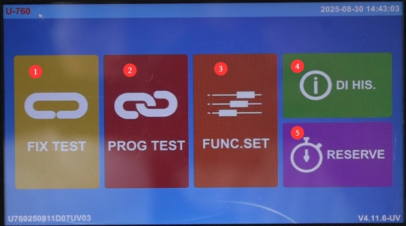
Şekil 6
4.2 Kalibrasyon Testi
4.2.1 Kalibrasyon Test Ekranına Giriş
Click “Constant-Value Test.” ① Test chamber temperature display; ② Test chamber temperature setting; ③ Black plate temperature display;④ Blackboard temperature setting; ⑤ UV irradiation intensity display; ⑥ UV irradiation intensity setting; ⑦ Control mode selection (three modes available: condensation, UV, and spray); ⑧ Parameter settings; ⑨ Test curve; ⑩ Start/Stop test.
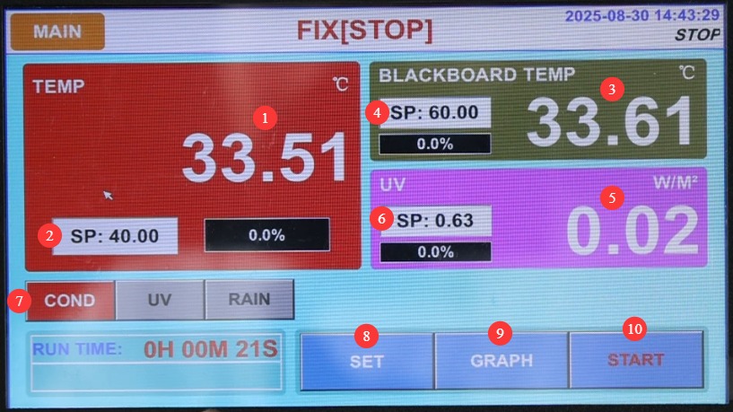
Şekil 7
4.2.2 Introduction to the Fixed-Value Parameter Settings Screen
Click “Settings.” ① For long-duration tests, set this to “ON” to configure the test duration; set it to “OFF” to stop the test manually. ② Spray settings: You can set the system to continuous or cyclic spraying.
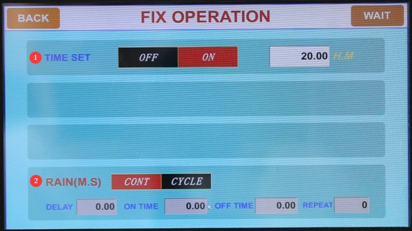
Şekil 8
4.2.3 Fixed-Condition Test in Condensation Mode
① Select the condensation mode; ② Simply set the temperature of the test chamber; ③ Once the test begins, the black panel heating and UV irradiation functions will not be activated.
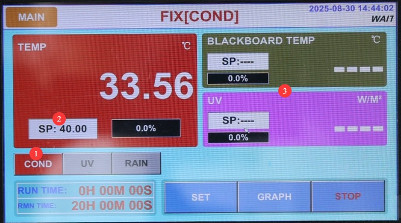
Şekil 9
4.2.4 UV Mode Calibration Test
① Select UV mode; ② Set the test board temperature; ③ Set the UV light intensity.
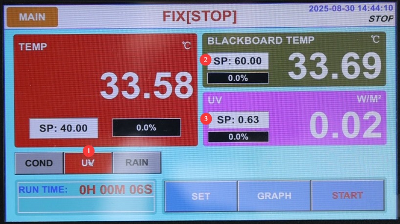
Şekil 10
① Click “Start Test”; ② Once the test begins, the temperature inside the test chamber will not be displayed; simply monitor the temperature on the blackboard and the UV light intensity.
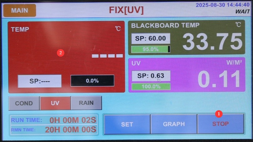
Şekil 11
4.2.5 Spray Mode Calibration Test
When the spray mode is selected, after the test begins, the test chamber temperature, black panel temperature, and UV irradiation functions will not be activated; only the spray test will be conducted.
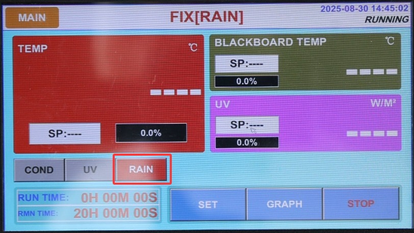
Şekil 12
4.3 Program Testi
4.3.1 Introduction to the Program Test Screen
Click “Program Test.” ① Select and display the program number currently being executed; ② Display the segment number currently being executed; ③ Edit the program.
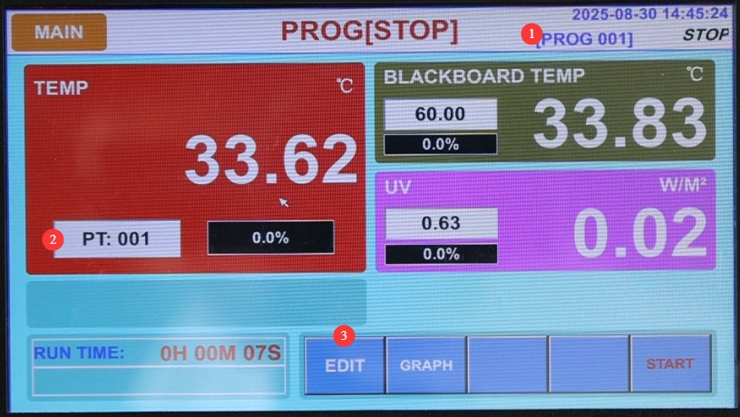
Şekil 13
4.3.2 Program Düzenleyici Ekranına Giriş
Click “Edit.” ① Enter the program number you want to edit; be sure to avoid duplicating existing program numbers. You can set up to 120 programs. ② Customize the program name. ③ Number of cycles; if no cycles are needed, enter 1.④ Link programs: If this program needs to automatically link to another program upon completion, enter the corresponding program number; otherwise, enter 0; ⑤ Switch to another test segment; ⑥ Set the test mode for this segment: condensation, UV, or spray;⑦ Test duration—set the duration for any test segments that are not required to -0.01; ⑧ Chamber temperature setting; ⑨ Black plate temperature setting; ⑩ UV irradiance setting; 11 Spray function switch—if this test segment involves spraying, set the spray function switch to ON.
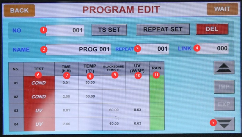
Şekil 14
Note 1: If temperature or light intensity needs to be set for this test segment, the same parameters must be set for both segments. Segment 1 is the transition phase; set the test duration to 1 minute (the actual duration may exceed 1 minute), during which the test chamber will reach the required temperature or light intensity as quickly as possible. Segment 2 is the actual test phase; set the test duration to the required length. See the figure above.
4.3.3 Wait Function Settings
Sağ üst köşedeki "BEKLE" seçeneğine tıklayın.
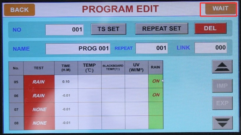
Şekil 15
① The wait function must be enabled during program testing; ② Temperature wait range: If set to 2°C, the target temperature is considered achieved when the actual temperature differs from the target temperature by 2°C; ③ UV irradiance wait range: If set to 0.1, the target irradiance is considered achieved when the actual irradiance differs from the target irradiance by 0.1;④ Maximum wait time: If the target value is not reached within the maximum wait time, that segment will be skipped.
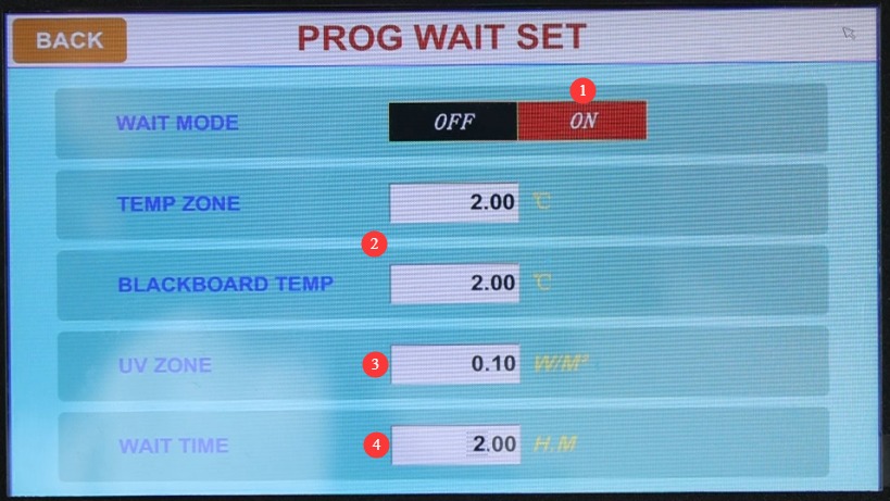
Şekil 16
The wait function is primarily used during transition phases in the program; that is, once the test chamber reaches the set temperature and light intensity, it automatically skips the transition phase and proceeds to the next phase for the formal test.
4.3.4 Program Testi
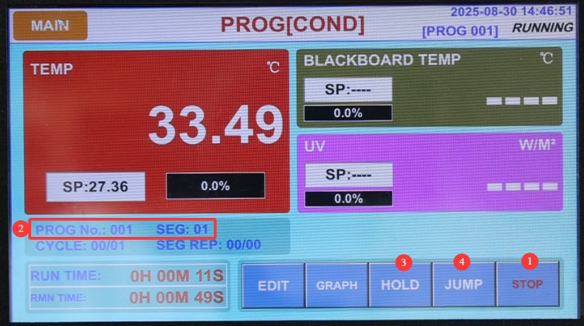
① “Başlat”a tıklayın; ② Geçerli program numarasını ve segment numarasını görüntüler; ③ “Basılı Tut” seçeneği, bu işlevi iptal etmek için tıklayana kadar programın geçerli test segmentini çalıştırmaya devam etmesini sağlar; ④ “Segmenti Atla”: Geçerli test segmentini atlamak için tıklayın.
Şekil 17
4.4 Çalışma Ayarları Ekranına Giriş
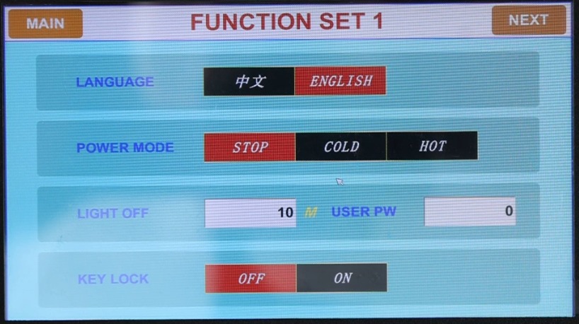
You can configure the display language and power-off restart mode (Stop: After a power outage during operation, the system returns to the “Stop” state when power is restored; Cold Start: After a power outage during operation, the system restarts from the first section and resumes operation when power is restored; Hot Start: After a power outage interrupts operation, the system continues from the section where it left off before the outage; when power is restored, the system returns to the state it was in before the outage) and other settings.
Şekil 18
4.5 Introduction to the Fault Log Screen
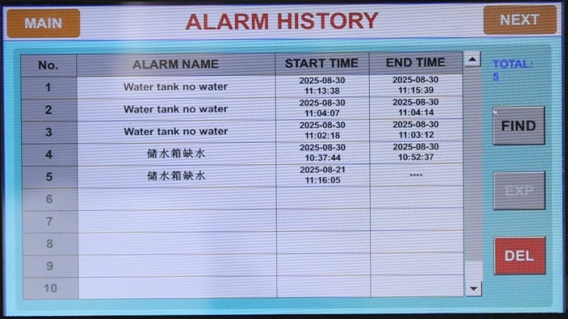
Geçmiş arıza kayıtlarını görüntüle.
Şekil 19
4.6 Randevu Ayarları Ekranına Giriş
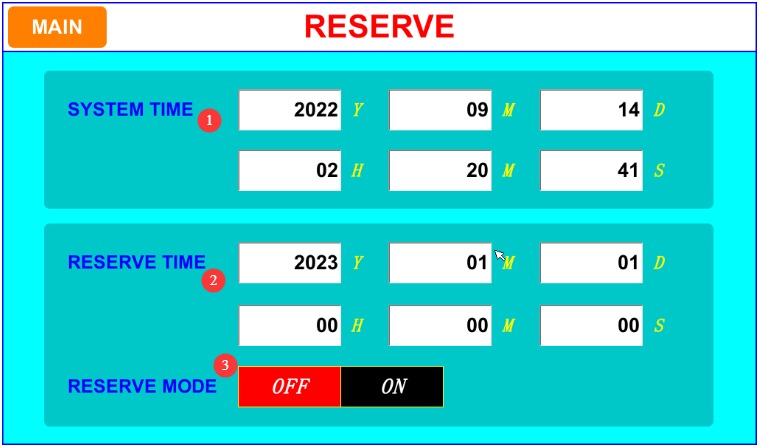
① Set the system’s current time; ② Set the scheduled time; ③ Scheduled operation feature: Once enabled, the device will automatically run the currently selected test at the scheduled time.
Şekil 20
4.7 Monitoring the Test Operation Process
Keep an eye on the water level in the tank; during the condensation test, the water level will drop as water evaporates. Please refill the tank promptly when the water level drops.
5. Test Sonrası Prosedürler
5.1 Termination of the Test
Testin normal şekilde tamamlanmasını bekleyin; ardından cihaz bekleme moduna geçecektir. Testi erken sonlandırmanız gerekiyorsa, ilgili ekrandaki "Durdur" düğmesine tıklayın ve cihaz bekleme moduna geçecektir.
5.2 Örnek Alma ve İşleme
Wear protective gloves, open the test chamber door, remove the sample, and place it in the designated area. Record any changes in the sample’s appearance (such as fading or cracking), and conduct subsequent analysis in accordance with the test standards.
Not: UV lambası açıkken test odasının kapağını açmayın.
5.3 Immediate Cleaning of Equipment
Numune rafını ve ekipmanın iç yüzeylerini temiz bir bezle silerek kalan toz veya numune artıklarını temizleyin.
Tanktaki su seviyesini kontrol edin. Su seviyesi düşükse, standart seviyeye kadar arıtılmış su ekleyerek tamamlayın (bir sonraki kullanım için hazır hale getirin).
If a spray test has been performed, open the drain valve to empty any remaining water from the tank, clean the tank, and then refill it with water.
5.4 Exporting and Saving Data
Verify that the USB flash drive is connected, go to the “Historical Data” or “Curves” screen, and select the test data or curves you want to export.
Click the “Export” button, wait for the export to finish, then safely remove the USB drive and back up the data to your computer.
Record key test information (such as program number, test duration, sample name, etc.) to facilitate subsequent traceability.
5. 5 Shutting Down the Equipment
If no further testing will be conducted that day, please turn off the test chamber and switch off the main circuit breaker on the back.
6. Ekipmanların Günlük Bakımı ve Onarımı
6.1 Düzenli Temizlik
Haznenin Temizlenmesi: Hazneyi 3-6 ayda bir temizleyin. Güç kaynağını ayırdıktan sonra, numune rafını çıkarın ve yüzen kalıntıları ve katı kirlilikleri gidermek için numune rafını, su tepsisinin altını ve haznenin iç duvarlarını silin.
Tank Cleaning: Clean the tank once a month. Drain any accumulated water from the tank, then wipe down the inside walls with a clean cloth to remove scale and debris, preventing clogs in the nozzles or damage to the water pump.
Nozzle Cleaning: Inspect the nozzles once a week. If you notice uneven spraying or no water coming out, rinse the nozzles with clean water to remove any blockages (do not use hard objects to clear blockages).
Dokunmatik Ekranın Temizlenmesi: Kuru ve temiz bir bezle silin ve nemin ekranın girintilerine sızmasını önleyin.
6.2 Maintenance and Replacement of Light Tubes
Işık tüplerinin görünümünü haftalık olarak kontrol edin. Herhangi bir çatlak, renk değişimi veya anormal titreme fark ederseniz, bunları derhal değiştirin.
Record the cumulative operating time of the lamp. When the irradiance drops significantly (below 80% of the set value), the lamp must be replaced even if it is not yet damaged.
When replacing the fluorescent tubes, remove the panels on both sides of the unit and unplug all the lamp sockets at both ends of the corresponding tubes, as shown in the figure below:
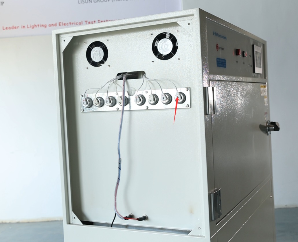
Şekil 21
Ardından, test odasının içinden floresan tüpü yavaşça çevirerek dışarı çekin. Yeni floresan tüpü aynı yöntemle takın.
6.3 Equipment Storage and Maintenance During Idle Periods
Short-term storage (within 1 month): Drain any water from the water tank and drip tray, clean the inside and outside of the equipment, disconnect the power supply, leave it in its original location, and ventilate the area regularly.
Uzun süreli kullanılmama (1 aydan fazla): Yukarıda belirtilen adımlara ek olarak, kapasitörler gibi elektrikli bileşenlerin bozulmasını önlemek için ekipman ayda bir kez açılmalı ve en az yarım saat çalışır durumda bırakılmalıdır.
Before restarting: Check the power supply, piping, and the condition of the fluorescent tubes; clean the water tank and refill it with water; conduct a 30-minute test run to ensure there are no abnormalities before proceeding with the formal test.
7. Sık Karşılaşılan Sorunların Giderilmesi ve Çözülmesi
7.1 Startup Failures
7.1.1 Symptoms: The device fails to start, and the power indicator light does not illuminate.
Olası nedenler: Arızalı bir harici güç anahtarı, atmış bir devre kesici veya gevşek bir elektrik fişi.
Solution: Check that the power plug is securely plugged in, and test the unit by plugging it into a different outlet; if the circuit breaker trips, check for a short circuit and then reset it; if the power switch is damaged, contact the manufacturer for repairs.
7.1.2 Symptom: The power indicator light is on, but the touchscreen does not respond
Olası nedenler: Dokunmatik ekran kalibrasyon hatası, kontrol ünitesi arızası.
Solution: Disconnect the power supply for 3 minutes, then reconnect it; go to the second screen in the operation settings to calibrate the touchscreen; if calibration fails, contact the manufacturer to have the controller repaired.
7.2 Operational Failures
7.2.1 Fault Symptom: Temperature/Irradiance Does Not Reach the Set Value During Operation
Possible causes: Aging lamp tubes, heater malfunction, sensor malfunction, or ambient temperature outside the specified range.
Solution: Check the total operating time of the lamp and replace it if necessary; ensure the ambient temperature is between 5 and 27°C and that ventilation is adequate; if the sensor or heater is malfunctioning, contact the manufacturer for repairs.
7.2.2 Fault Symptom: An alarm is triggered during operation
Possible causes: Low water level in the tank, loose connection in the lamp tube, or parameter settings outside the specified range.
Troubleshooting: View the alarm log screen to identify the type of fault; if the water tank is low on water, refill it with purified water; if there is a loose connection with the lamp tube, unplug and replug it; if the parameters are out of range, enter the settings menu and adjust them to the appropriate range.
7.3 Sprinkler System Malfunction
7.3.1 Symptom: Insufficient spray pressure; water flow is too weak
Possible causes: The water pump pressure is not set correctly, the water level in the tank is too low, or the nozzle is clogged.
Çözüm: Basıncı artırmak için pompanın üzerindeki basınç vanasını saat yönünde çevirin; su deposunu standart seviyeye kadar doldurun; ve nozullardaki tıkanıklıkları giderin.
7.3.2 Symptoms: The pump starts but no water is sprayed
Olası nedenler: Pompanın içinde su olmaması, boruların tıkanması veya nozulun tamamen tıkanması.
Solution: Disconnect the power supply and pour purified water into the pump’s inlet; check that the spray lines are clear; thoroughly clean or replace any clogged nozzles.
7.4 İletişim Arızaları
7.4.1 Symptoms: The touchscreen displays “————,” and the data does not update.
Olası nedenler: Kontrol ünitesi ile kontrol kartı arasındaki zayıf bağlantı; hasarlı iletişim hatları.
Çözüm: Güç kaynağını ayırın, dahili iletişim kablolarının gevşek olup olmadığını kontrol edin ve gerekirse yeniden bağlayın; kablolar hasarlıysa, değiştirilmesi için üreticiyle iletişime geçin.
7.5 Data Export Issues
7.5.1 Symptoms: Unable to export data or curves
Possible causes: The USB flash drive is not formatted, poor contact at the USB port, or insufficient storage space on the device.
Çözüm: USB sürücüsünü FAT32 olarak biçimlendirin, ardından yeniden bağlayın; farklı bir USB sürücüsü deneyin; depolama alanını boşaltmak için bazı eski verileri silin.